Beta available now — a 30-day free trial with every add-on included. No card, no account. Start your free trial →
Sheet.Developments

Beta out now 30-day free trial

Flat patterns, and the job around them

Patterns that fit, first time.

Sheet.Developments unrolls the parts a fabrication shop actually makes: cones, hoppers, lobster-backs, tank heads, square-to-rounds, rectangular ductwork and the cladding that goes round it all. Then it prices the job, prints the shop's paperwork and tracks the parts across the floor. Windows desktop, works offline, no subscription to your own drawings.

The beta is out now: 30 days free with every add-on switched on. No card, no account.

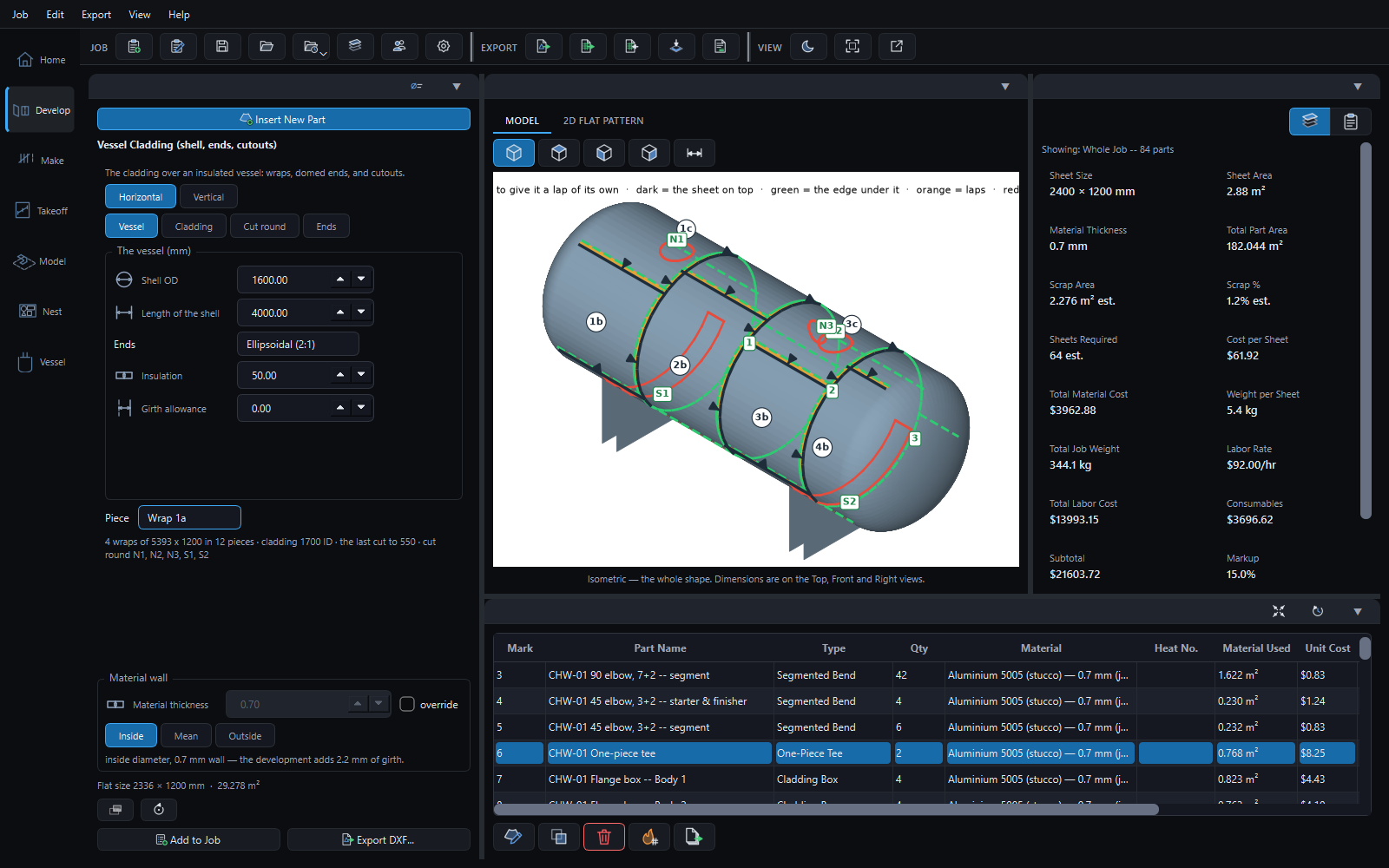
Sheet.Developments with a clad buffer tank in 3D: numbered wraps, the cutouts round its nozzles and saddles, the job's parts listed underneath and the job priced on the right
84parts from six lines and a tank 561blanks to cut 182.0 m²of 0.7 mm stucco $21,603before markup, labour in

The chilled water buffer tank from the tutorial's insulation job: 1600 OD by 4 m under 50 mm of insulation, every wrap numbered and the cutouts round its nozzles and saddles marked, with the whole plant room priced beside it.

Three trades, one program

Whatever you roll, fold or clad.

The same program runs an insulation contractor's cladding, an HVAC shop's ductwork and a plate shop's vessels. Each gets the tools its own work needs, and all three share the job, the pricing and the paperwork.

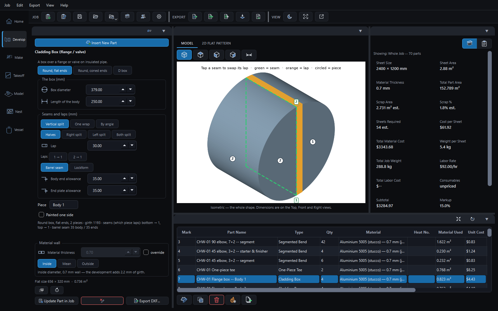
A cladding box over a flange in 3D, split in halves with its laps shown in orange and each piece numbered

Insulation cladding

A line list in. A priced job, a cut list and labels out.

  • The cladding take-off turns metres, bends, tees, flanges and valves into every part, marked and counted
  • One-piece tees, flange and valve boxes, and whole vessels with cutouts round the nozzles
  • Labour by fitting, and the rivets, bands, sealant and insulation priced from your own table
  • Scan each label on the Make page as it is cut and formed
Everything for insulation →
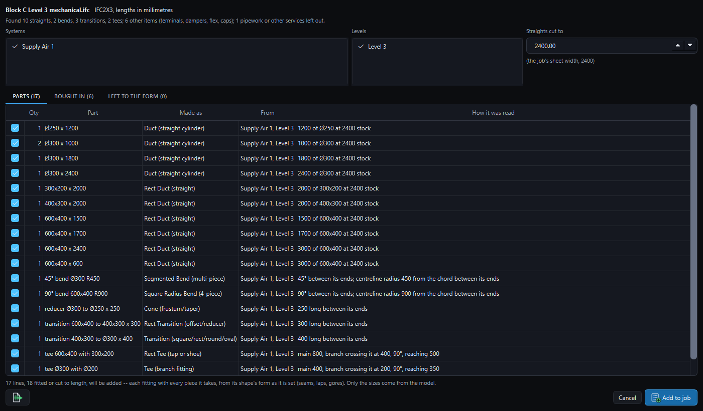
The IFC import review listing each duct and fitting from a building model with how it was read

HVAC ductwork

From the consultant's model and the builder's drawings.

  • Model the ductwork in 3D, on levels and grids, and the job is made from it (Model space)
  • Import an IFC model: every duct and fitting, sizes carried through, straights cut to your stock, or placed in 3D with Model space
  • Your shop's seams: Pittsburgh, snap lock, button punch, standing and grooved, slip and drive with the cleats cut
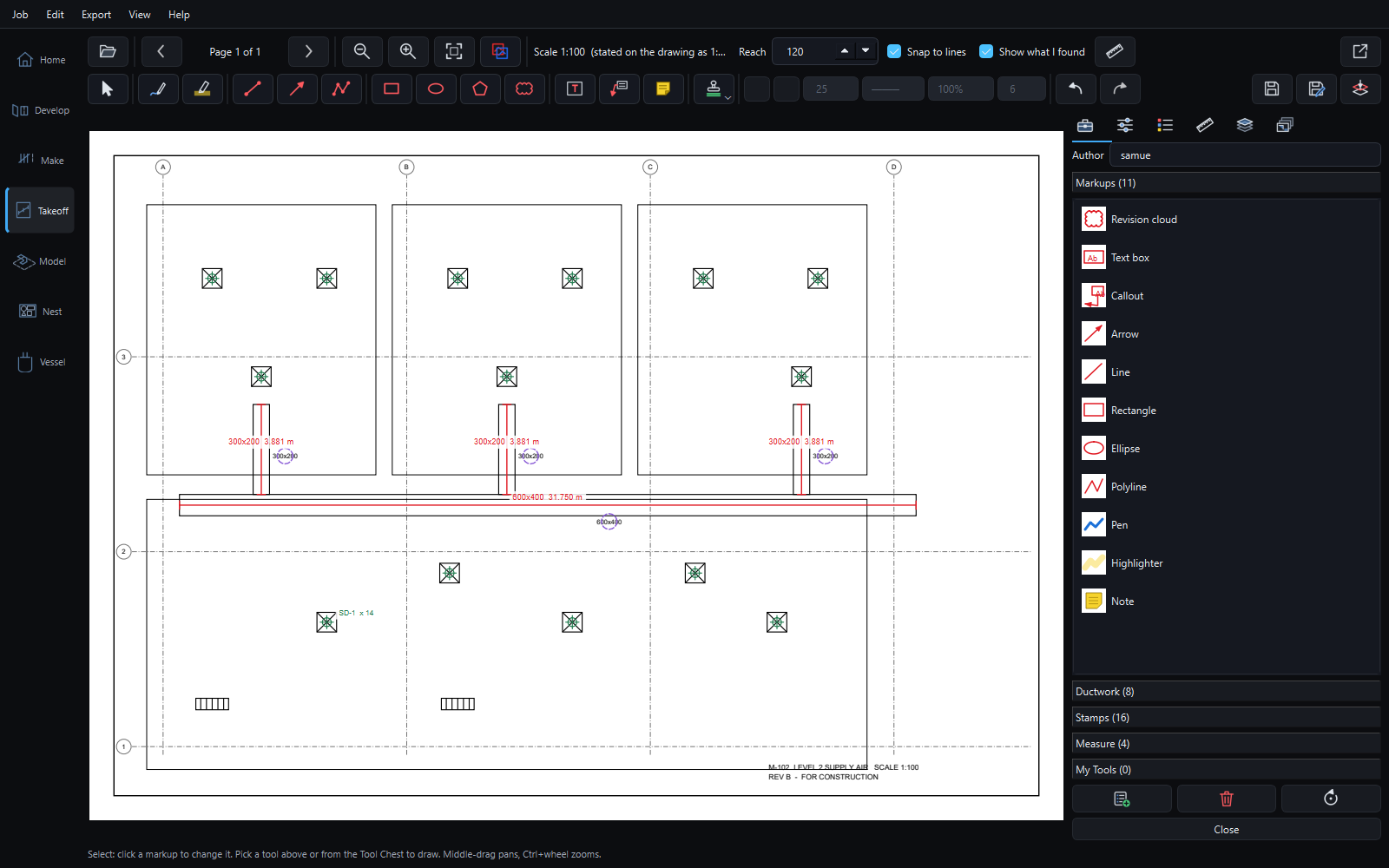
  • Measure and count straight off the PDF, compare revisions, keep a floor's drawings as one set
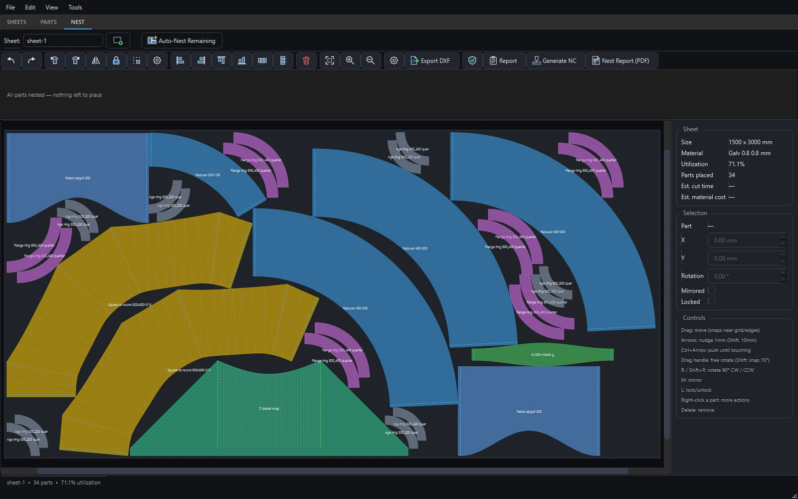
  • Duct board panels nested and shown in 3D as the router cuts them
Everything for HVAC →
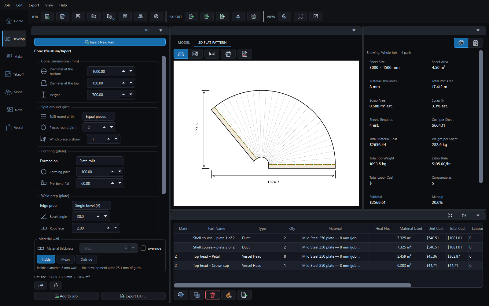
A plate cone developed flat with roll lines across it and a pre-bend flat past each seam

Plate and pressure vessels

Rolled, pressed, bevelled and traced to the heat.

  • Roll lines and pre-bend flats for the rolls, or a bump schedule for the press brake
  • Weld prep bevels on every butt edge, on their own DXF layer
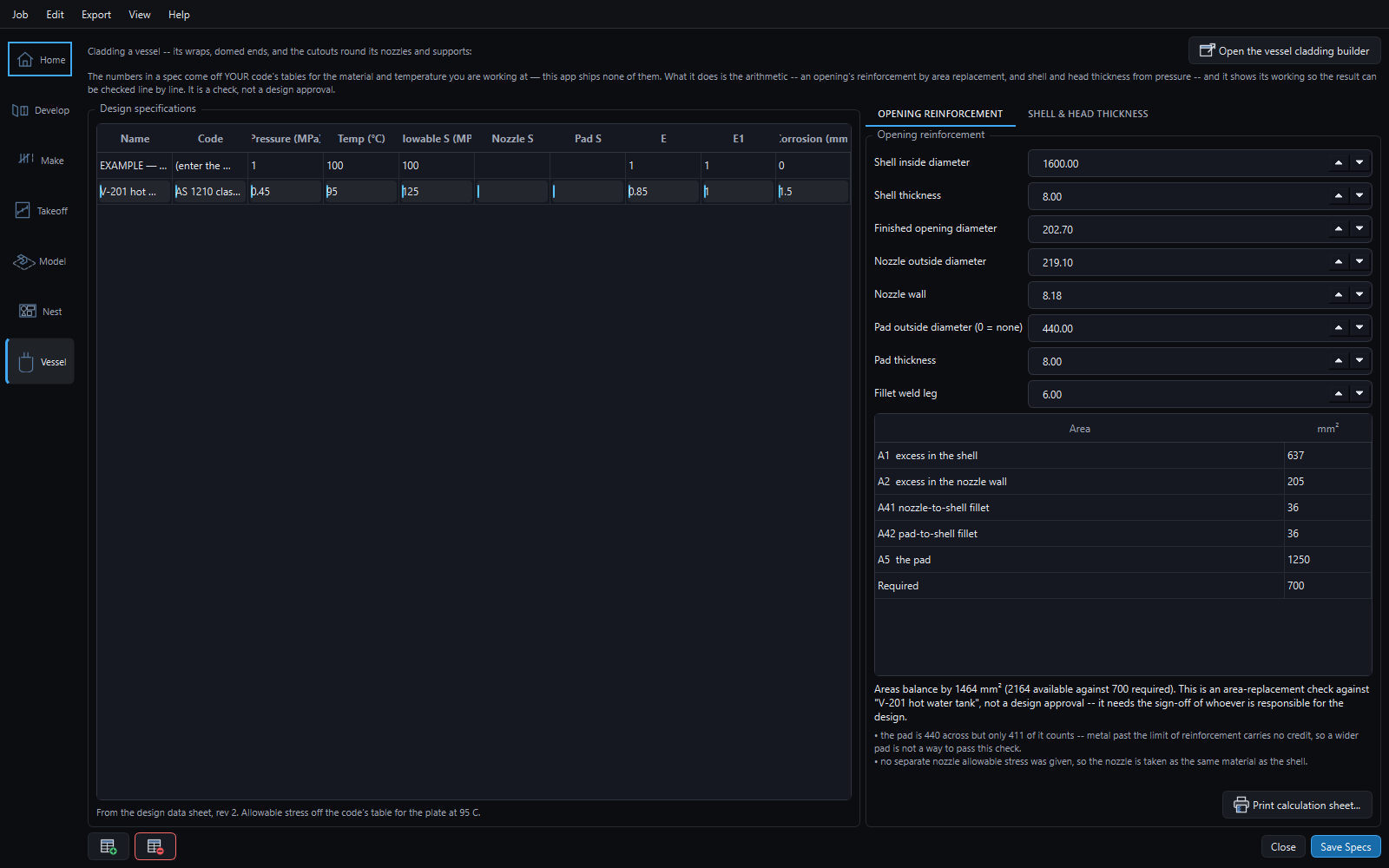
  • Shell and head thickness from pressure and the nozzle reinforcement, printed for sign-off
  • Heat numbers from the plate to the labels; STEP out for fit-up in your CAD
Everything for plate →

One chain, nothing retyped

From the drawing to the shop floor.

Every job in the tutorial went from its source to the shop floor without a number being typed twice: a line list, a building model and a PDF set, and a design data sheet.

  1. Take off

    In

    A line list, an IFC model, a CSV, or the builder's PDF measured on screen.

  2. Develop

    Unroll

    Every part on the middle of the metal, with its seams, laps and bevels.

  3. Price

    Quote

    Material, labour by fitting and consumables, into a quote on your letterhead.

  4. Paperwork

    Print

    DXFs on layers, the cut list, labels, marking-out sheets and full-size prints.

  5. Nest

    Cut

    Onto your sheets and plate, with the program for your table.

  6. Make

    Track

    Scan each label as it is cut, formed, assembled and shipped.

The job

Laying out a cone by hand is an afternoon. Getting it wrong is a plate.

Triangulation on the shop floor works. It has for a century. But it is slow, it does not scale to a job with forty-one fittings, and every transcription is a chance to be out by a few millimetres. General CAD will draw you the solid and then leave you to work out the development yourself.

This does the development. Type the sizes off the drawing, check the 3D model to see you have described the right part, and take the flat pattern away as a DXF, a marking-out sheet or a full-size paper template.

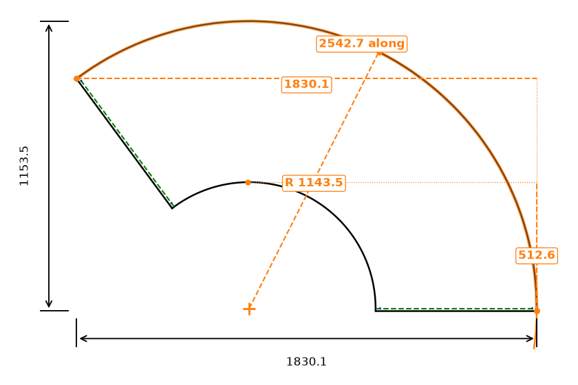
A cone development on screen with its girth along the arc, radius, width and height measured, and the measurements listed beside it

A cone development measured on screen: the girth along the outer arc, its radius, and the blank's width and height. Measuring along a curve follows the metal, so it reads the rolled circumference, 2542.7, not the 2050.3 straight across.

New Add-on

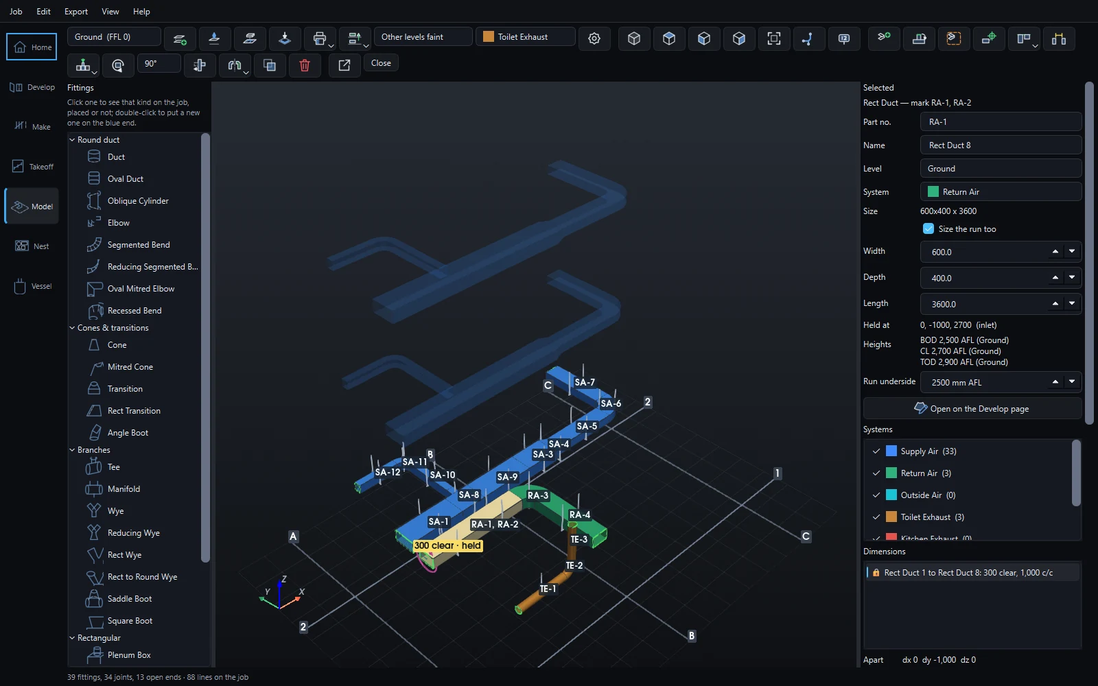
Model the ductwork. The job builds itself.

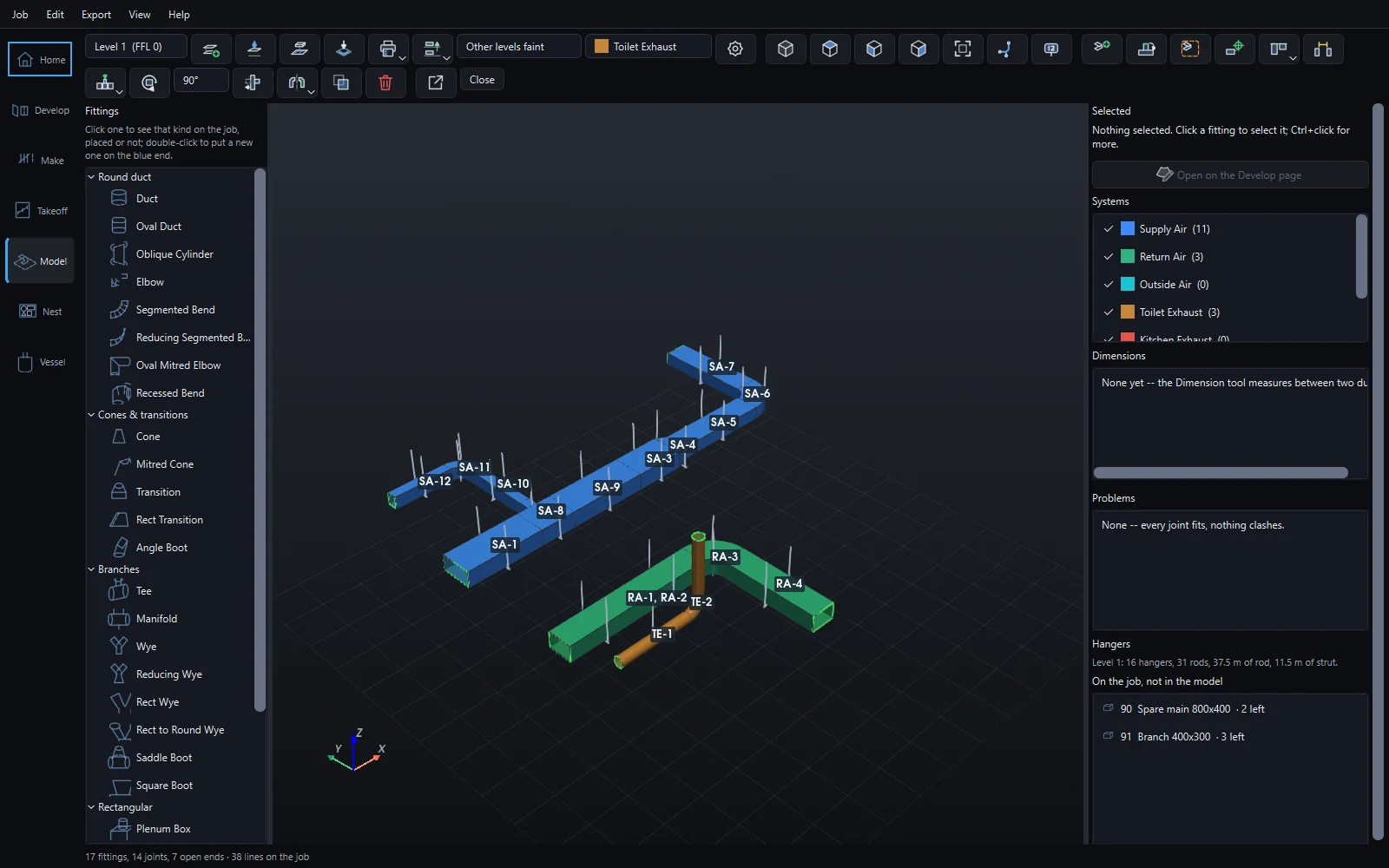
Lay the runs out in 3D the way they go up: piece by piece off the open end, on the right floor, in each system's colour. Every fitting you place is a part on the job, wearing the number you gave it and developed flat for the shop.

  • Levels, grids and RLs for a tower or a plant: ceiling voids, typical floors copied up, a site datum.
  • Set out exactly. Move to a grid line, dimension to the next duct, lock it, and it holds.
  • Clashes in red as you draw, against the clearance you set.

See Model space

The Model page: supply and return runs on the ground floor with their part numbers, the supply copied faintly onto two floors above, grid lines with their bubbles, and a dimension holding the return 300 clear of the supply

Ground and two typical floors on a grid, the supply copied up, the return held 300 clear of it.

The library

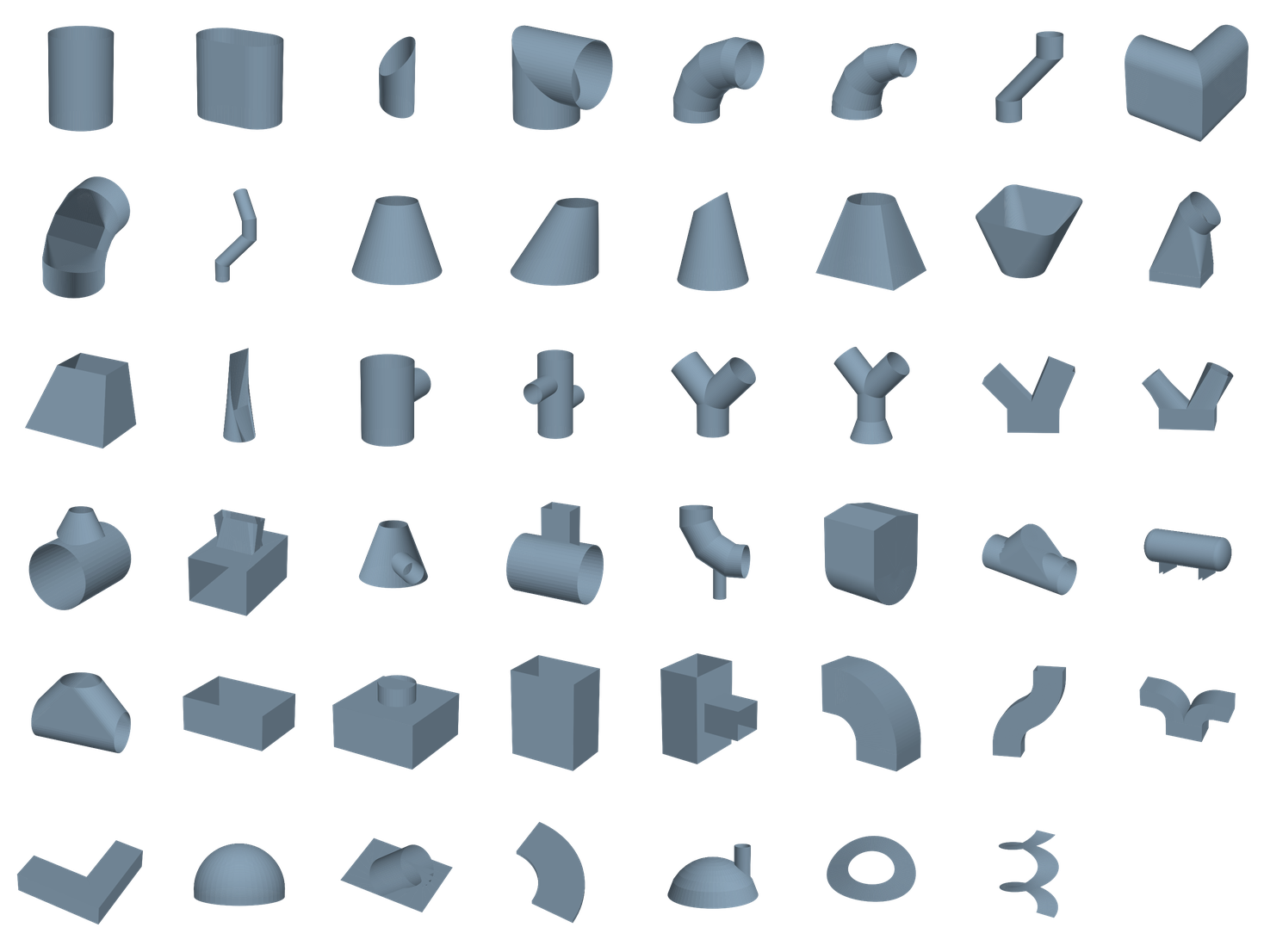
Forty-seven shapes, grouped the way you'd ask for them.

Every one developed properly: true lengths, neutral-axis girths, seam laps and end allowances on all four edges, and a girth split when the part is bigger than your plate.

Round duct: straight, oval, oblique, elbows, lobster-backs, reducing gore bends, mitred offsets, oval elbows, flat-spot bends, compound runs Cones & transitions: concentric, oblique, mitred, square-to-round, any two ends in any two planes, rectangular, angle boots Branches: tees, manifolds, wyes, reducing wyes, rect and rect-to-round wyes, saddle boots, square boots, cone-to-pipe, rect into round main, trunnion supports Cladding: one-piece tees, boxes over flanges and valves (round with flat or coned ends, and D boxes with a fall on the top), and whole vessels: wraps, domed ends, and cutouts round nozzles, saddles and legs Rectangular: ducts, tees, radius bends, offsets, bullheads, mitred elbows, pans, and plenums: cushion heads and boxes closed all round, rectangular or pentagon, with their spigots Vessels & plate: dished heads in straight or spiral petals, nozzles through heads, compensation plates, holes through plate, ring segments Screw flights: parallel and tapered
The forty-seven shapes in the library, shown as shaded 3D renders

The general transition

The fitting that is not on anybody's list.

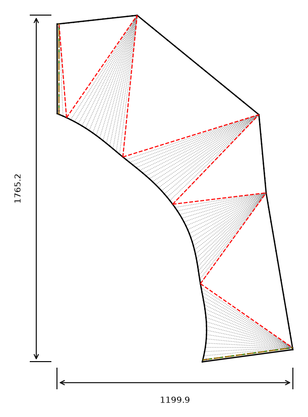
Every shop gets them: a hopper with radiused corners, a fan inlet whose top sits at an angle, an adapter onto a D-shaped flange. Give each end its own outline (round, a rectangle with a corner radius, a flat oval, a polygon, or your own corner points typed in), lean it and turn it, and it lays the metal out flat.

It works out which parts of the surface stay flat and which roll, so straight sides come out as true flat panels and corners as cones. The blank marks every fold with its angle and every line where the rolling starts, and the marking-out sheet carries a table of true lengths for laying it out by hand, step by step from the seam.

The general transition: a round 500 bottom and an 800 by 400 rectangular top leaning 30 degrees, developed flat with red lines marking where rolling starts and grey rulings through the rolled corners

Round 500 up to an 800 × 400 top leaning 30°: flat triangles on the straight sides, cones at the corners, and the red lines where the rolls take over. 1199 × 1770 flat, in 1.6 mm.

Why it fits

It knows what your diameter means.

Rolled metal stretches on the outside and compresses on the inside. The length that does neither runs up the middle of the material, so that is what the pattern has to be developed on. Most software assumes the number you typed was already that mean diameter. No drawing says mean diameter. It says 300 NB, or 300 ID, or 300 OD.

Tell it which, and it does the rest:

PartInsideMeanOutsideSpread
300 dia × 1.2 mm946.2942.5938.77.5 mm
600 dia × 3 mm1894.41885.01875.518.8 mm
900 dia × 6 mm2846.32827.42808.637.7 mm

Girth in millimetres. On thin duct a lap swallows the difference. On 6 mm plate it is a scrapped cylinder.

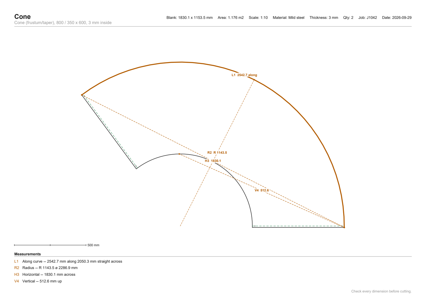
A marking-out sheet: the cone development drawn at 1:10 with its measurements listed underneath

The marking-out sheet. Drawn at a real, stated scale from the drawing-office run, never "shrunk to fit", with a scale bar that survives a photocopier. The next page is a table of offsets from a baseline, so any blank can be marked out on the plate with a tape and a square.

Cladding over insulation

Sized from the pipe, priced from the line list.

DN80 is not 80 mm. It is 88.9 mm of steel pipe, or 89.1 if it is JIS, and a 3" copper tube is something else again. Pick the standard and the size, give the insulation thickness, and it works out the cladding: round both sides of the insulation, plus the girth allowance your shop adds because rockwool is never quite its nominal thickness.

Steel pipe to ASME B36.10M and B36.19M, EN 10220, EN 10255 and JIS; copper to ASTM B88, EN 1057 and AS 1432; metric plastic pipe; and ASME and EN flange diameters for flange boxes. Every table checked against published tables for its standard, with where it came from written on it.

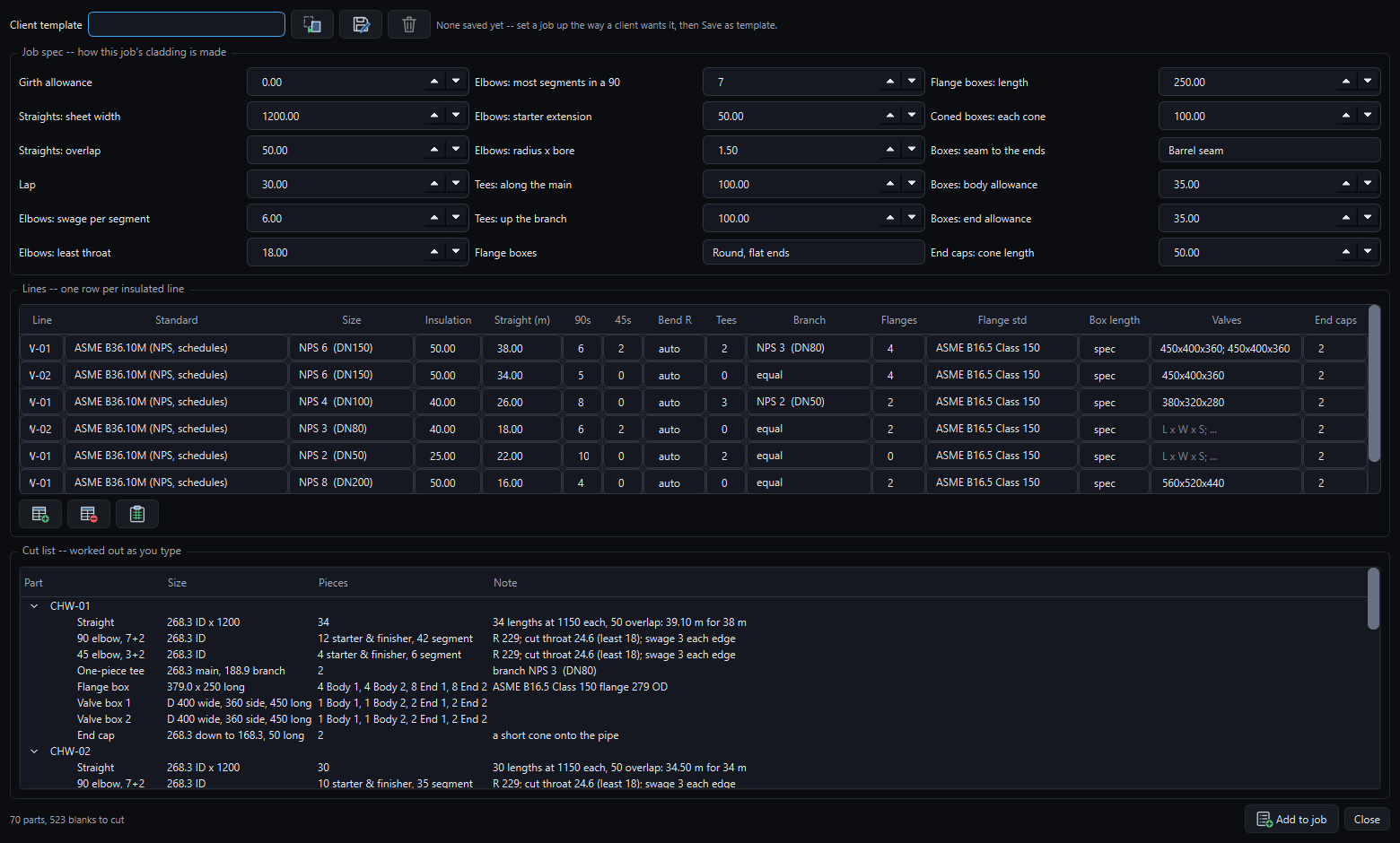
The cladding take-off: six insulated lines with their sizes, insulation, metres, bends, tees, flanges and valves, and the cut list worked out underneath

Six lines of chilled, heating and condenser water in, with the job's cladding spec above them: 70 parts and 523 blanks in the cut list underneath, worked out as the lines are typed.

A line list in, a cut list out

Each insulated line: pipe size, insulation, metres of straight, bends, tees, flanges, valves and end caps. Straights come out at your sheet width, elbows with the most segments your swage wheels can make, boxes sized off the flange tables. One click puts the lot into the job, marked and counted.

A client's spec, kept

How this client wants their cladding made (sheet width, overlap, lap, elbow segments, how boxes and tees are made) saved as a template and picked for the next job.

Boxes over flanges and valves

Round with flat or coned ends, or a D box with a fall to shed water. Split in halves or by angle, then tap each seam on the 3D model to choose which piece carries its lap. On pre-painted sheet the far end comes out mirrored.

Tees from one blank, vessels whole

The lagger's one-piece tee, equal or reducing, square or angled. And the cladding over a whole vessel: wraps, domed ends, and cutouts round its nozzles, saddles and legs.

In the shop

From the drawing to the plate without retyping anything.

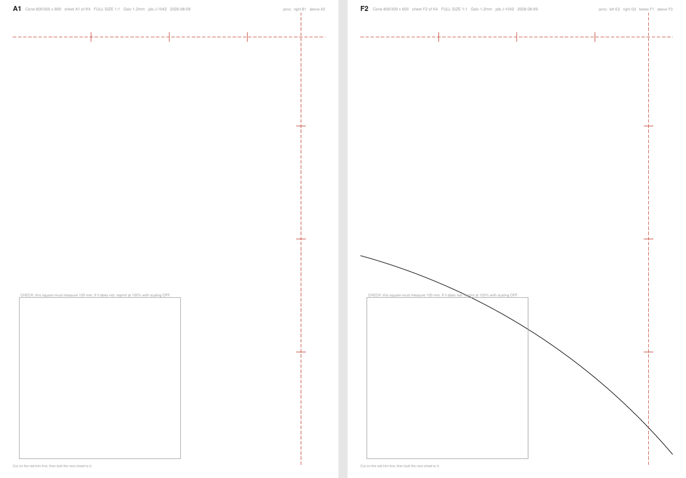
Two sheets of a full-size tiled print, with trim lines, registration marks and a check square

Full size across as many sheets as it takes. Tiles overlap and carry a trim line, so the join is exact whatever your printer's margins are, and every sheet has a 100 mm check square, because "fit to page" is on by default in half the drivers out there.

DXF that a cutter can actually use

Layers you control, arcs or polylines, mm or inches, your own part stamp. Bend, seam, bevel, guide and allowance lines each on their own layer, so nothing gets cut that shouldn't be.

Paper the shop can work from

A cut list and labels off the same numbers as the quote. Each label carries the mark, the part, its blank, its heat number and a QR code; marking-out sheets carry the measurements you placed and a scale bar.

Metric or imperial

Type 3-1/2, 3 1/2 or 3.5: all three work, and it reads back in fractions to the nearest 1/16. Everything is stored in millimetres underneath, so a job crosses between shops without changing size.

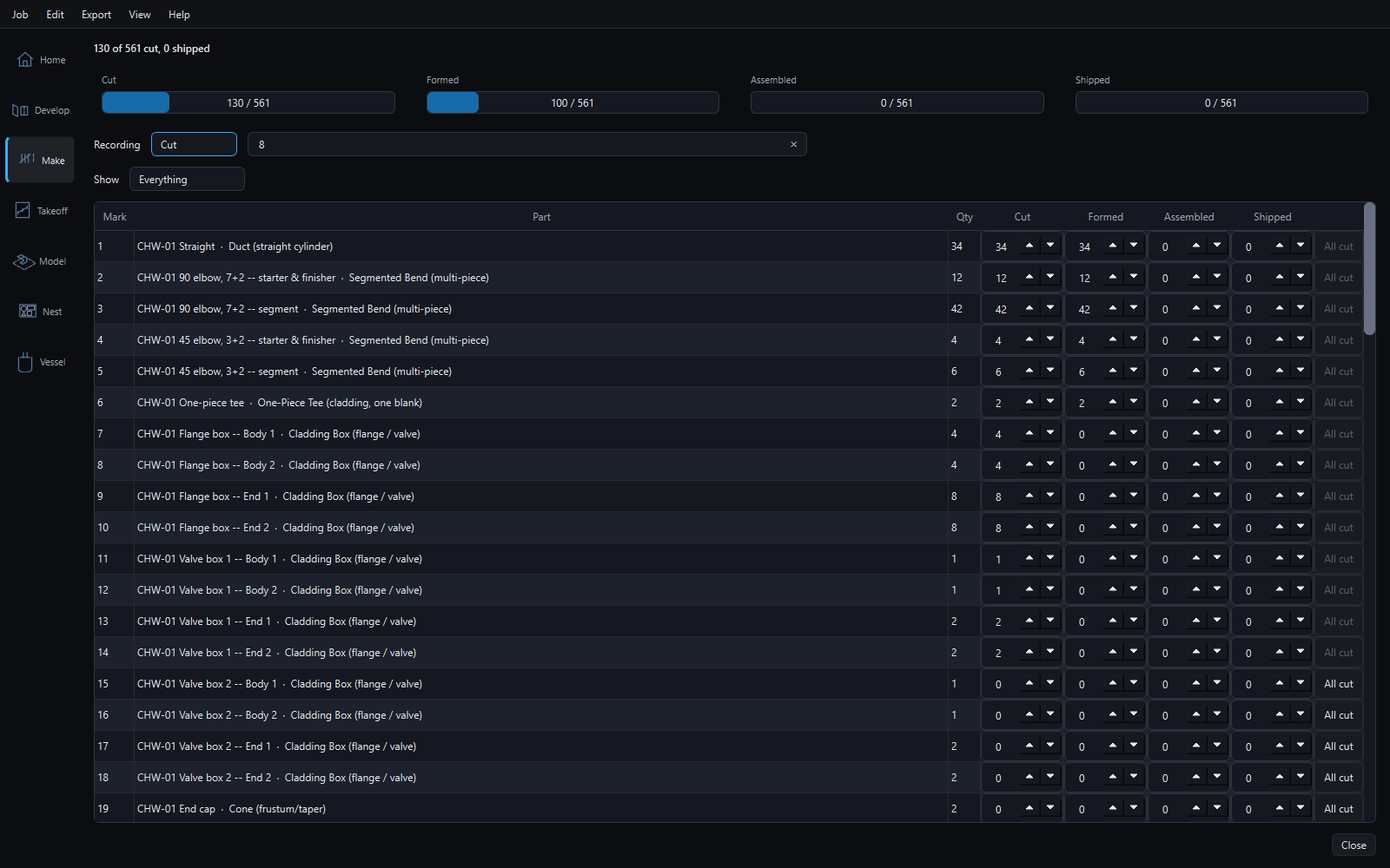
The Make page: each part with how many have been cut, formed, assembled and shipped, and bars totalling the job

The Make page on the plant room job: 130 of 561 cut. Scan a label, or type a mark, and the part is counted at the stage chosen.

A job you can keep track of

Parts carry a mark that survives editing and reordering, so drawing 14 is still drawing 14 after you delete drawing 3. Quantities, material and labour are editable in the table, and everything is undoable.

Shared between the office and the floor

Keep the job on the shop's drive and both can have it open. When one saves, the other is told who and when, and the changes merge. Every save is kept in the job's history, to compare, open as a copy or put back.

Parts too big for your plate

A blank that will not fit the job's sheet says so, and one click splits it round the girth into the fewest equal pieces that do, laps included. A segmented bend splits every gore into plates.

Add-ons

Four more, for the shops that need them.

Each opens a workspace of its own, on the same job. All four are in the free trial.

The tutorial

Watch it run four jobs, start to finish.

An insulated plant room, a hospital floor of supply ductwork, the same floor built in 3D over the builder's drawing, and a hot water tank in 8 mm plate, a step to a page. Every picture is the app itself, taken working through the jobs.

The same 49 steps are inside the program, under Help > Tutorial.

Read the tutorial (PDF, 7 MB)

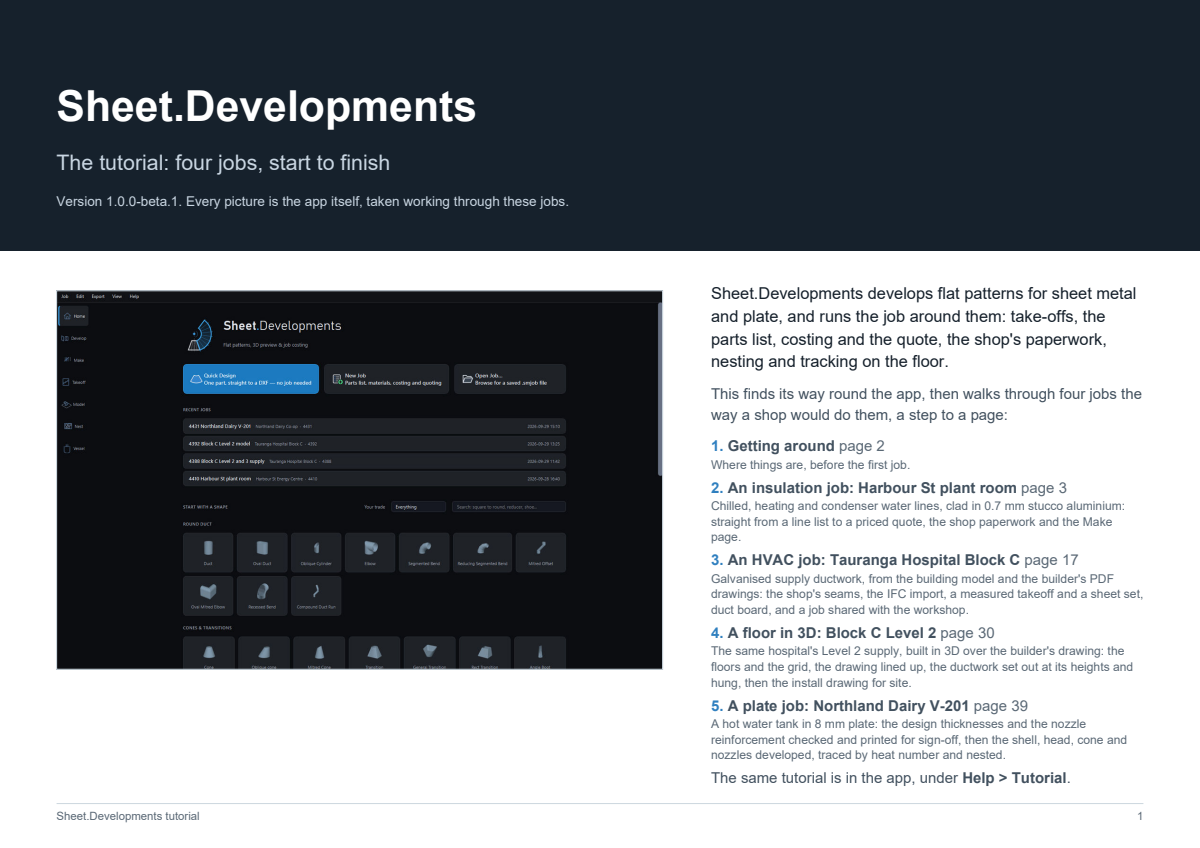
The tutorial's cover page, with the app's home screen and the contents

Pricing

Buy it once. It keeps working.

$TBCone-off, per machine; final price to be confirmed
  • All forty-seven shapes
  • DXF export with layers you control
  • Marking-out sheets, offsets and full-size prints
  • Pipe, tube and flange tables for cladding, and the cladding take-off
  • IFC import, costing, quotes, materials and customers
  • Shared jobs with a revision history
  • The Make page, labels and cut lists
  • Works offline: no account, no cloud
  • Free 30-day trial, every add-on included

A licence is tied to the machine it is activated on and works without an internet connection. Your jobs are plain files on your own disk; nothing is held hostage if you stop paying, because there is nothing to stop paying.

Beta testers get the launch price locked in. Model space, PDF takeoff, Nesting and Vessel calculations are add-ons on top.

Free 30-day trial

Want to try it on a real job?

The beta is out, and it is a free download. Put a real job through it and tell me what broke: I would much rather hear what is wrong with it than what is right.

Windows 10 or 11 · about 160 MB · version 1.0.0-beta.3

Tell me what you make (optional)

The three questions tell me whether the shapes you need are in there yet. If they are not, I would rather say so than waste your afternoon.

Thanks — I read every one, and I'll reply if there's anything you should know before you start.

I reply personally. Nothing else lands in your inbox, and your address goes to nobody.