
Develop
Shapes and flat patterns
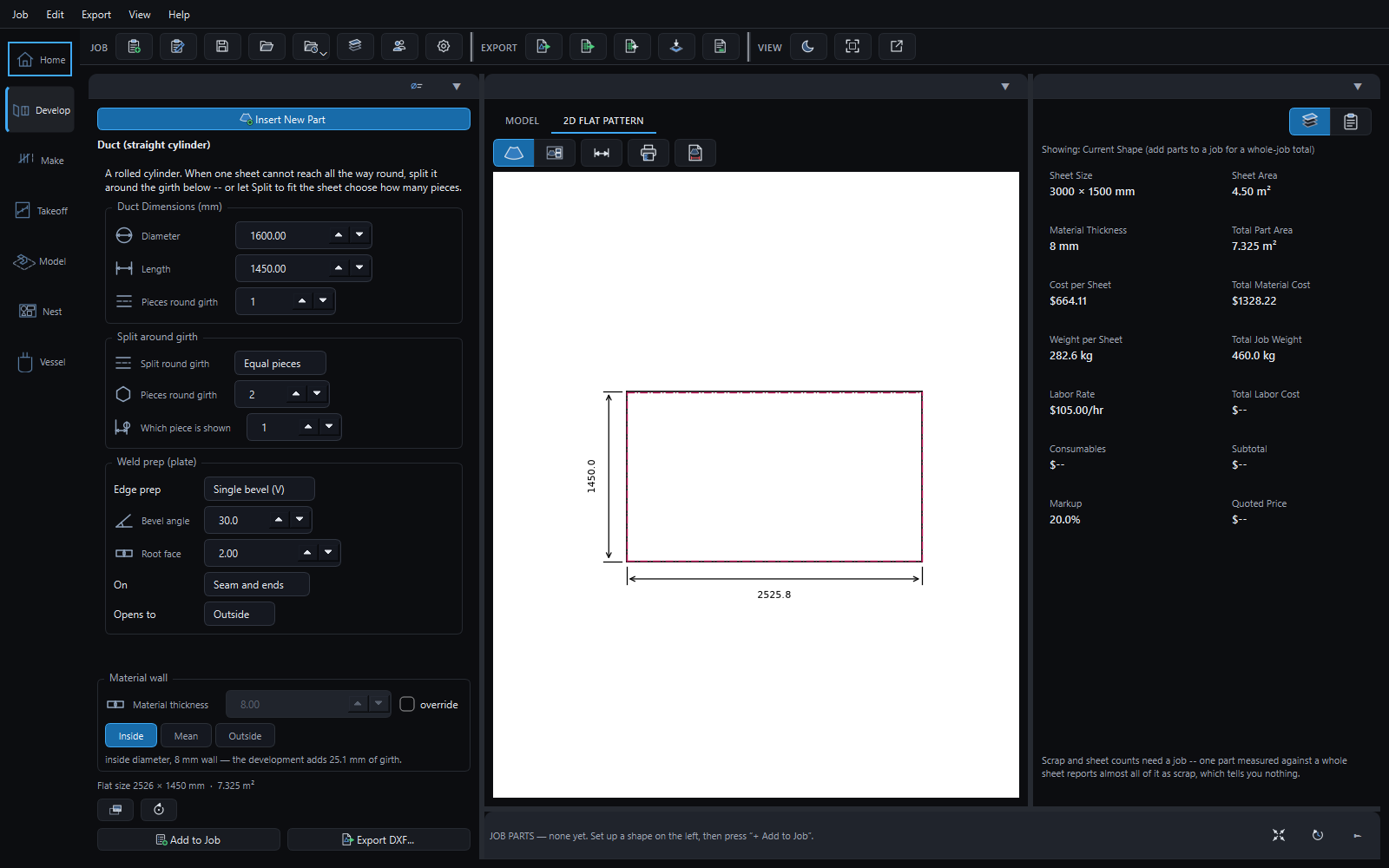
Forty-seven shapes, each developed properly: true lengths, girths on the middle of the metal, seam laps and end allowances on all four edges.

Forty-seven shapes, in seven groups
Round duct, cones and transitions, branches, cladding, rectangular, vessels and plate, and screw flights. Search for one by what you would call it: square to round, reducer, shoe.

The diameter you mean
Say whether a size is inside, mean or outside, and the girth is worked on the neutral axis for the thickness. On 6 mm plate that is 37.7 mm of girth on a 900 shell.

Seams, laps and holes
Butt welded or lapped, allowances on every edge, fixing holes along the laps, and holes in a face at real centres, for a flanged duct or an access panel.

Split to fit the sheet
A blank too big for the job's sheet is flagged, and one click splits it round the girth into the fewest equal pieces that fit, laps included. Gores split into plates; a branch fitting splits one component at a time.

Any two ends
The general transition: each end its own outline (round, a radiused rectangle, a flat oval, a polygon, your own points), leaned and turned. Flat panels come out flat, corners as cones, with a table of true lengths.
Work on the model
Tap a dimension on the 3D model to change it where it sits, tap a seam to move its lap, and measure the model itself. Look at it from the top, front, side or underneath.
Measure the blank
Click an edge to keep its size, or a corner then another for the distance. Along a curve it follows the metal, so a cone's girth reads round the arc.

Your fittings, kept
Save a fitting you make often as a preset beside the built-in ones. Set your thickness, laps and allowances once, and every new part starts there.

Insulation
Cladding over insulation
Sized from the pipe standard and the insulation, priced from the line list, and made the way your shop makes it.

Pipe and flange tables
Steel pipe to ASME B36.10M and B36.19M, EN 10220, EN 10255 and JIS; copper to ASTM B88, EN 1057 and AS 1432; metric plastic; ASME and EN flanges. The girth allowance over the insulation is a shop setting, set once.

The cladding take-off
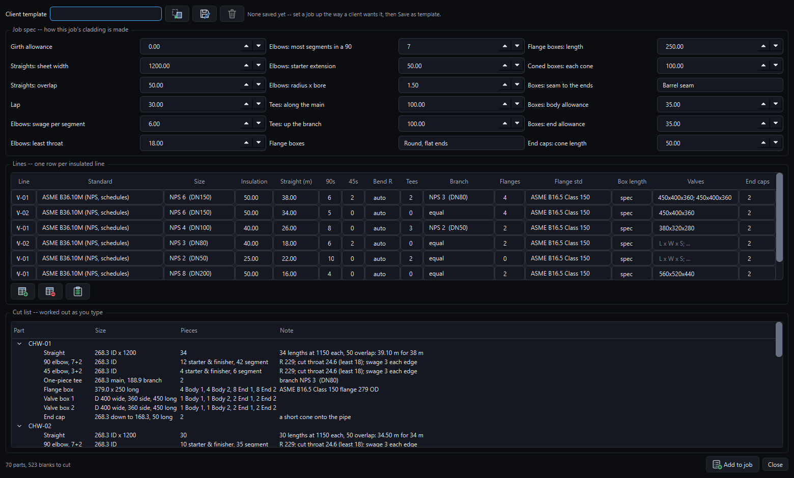
One row per insulated line: size, insulation, metres of straight, bends, tees, flanges, valves and end caps. Every part is worked out as you type, and one click puts the lot on the job, marked and counted.
A client's spec as a template
How a client wants their cladding made: sheet width, overlap, lap, elbow segments, how boxes and tees are made. Saved once, picked for the next job.
Flange and valve boxes
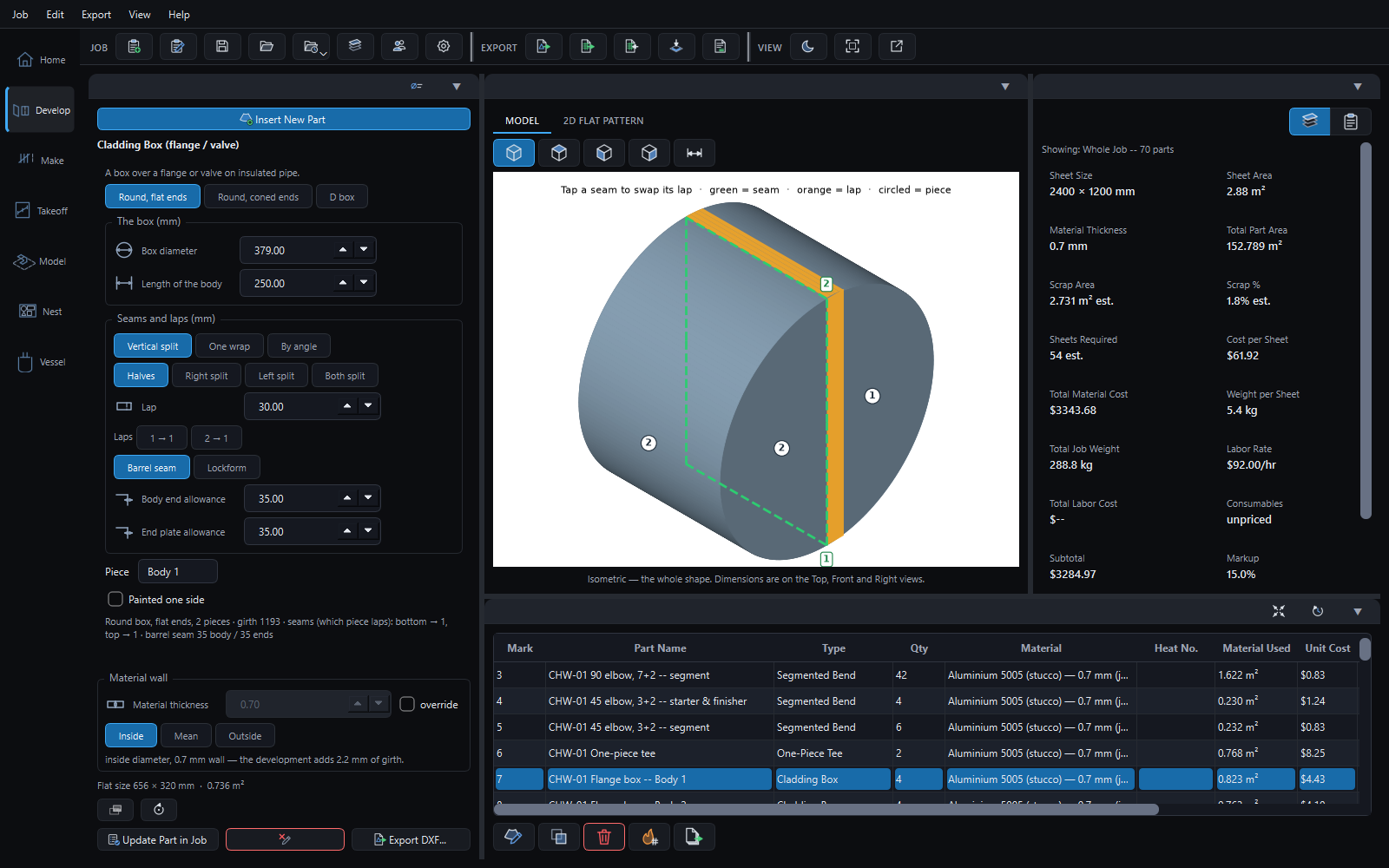
Round with flat or coned ends, or a D box with a fall to shed water. Seams in halves, by angle or at a height; tap a seam on the model to choose which piece laps. Mirrored for pre-painted sheet.
One-piece tees
The lagger's tee from one blank: the far half of the main rolled, a flat triangle up each side to the branch, a cone at every corner. Equal or reducing, square or angled.
Whole vessels
Horizontal or vertical: the wraps, the domed ends, and the cutouts round each nozzle, saddle and leg, every wrap numbered on the model.

HVAC
Ductwork
From the consultant's model and the builder's drawings, made with your shop's own seams.
Import an IFC model
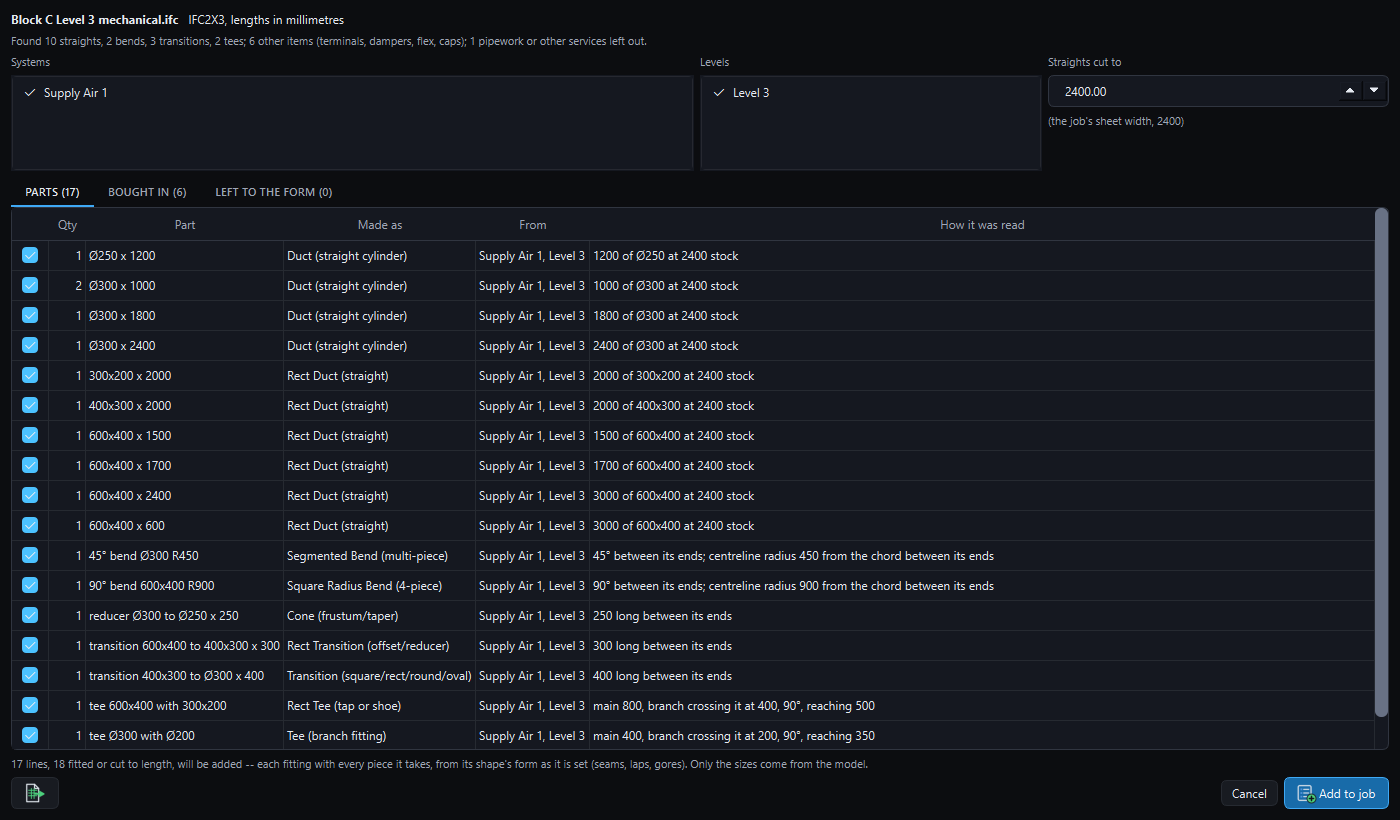
Every duct and fitting in the building model, IFC4 or IFC2x3: straights cut to your stock length, bends, transitions and tees with their sizes carried through. Each shows how it was read; diffusers and dampers are listed as bought in. Nothing is added until you say. With Model space it can go straight into the 3D model instead.
The seam library
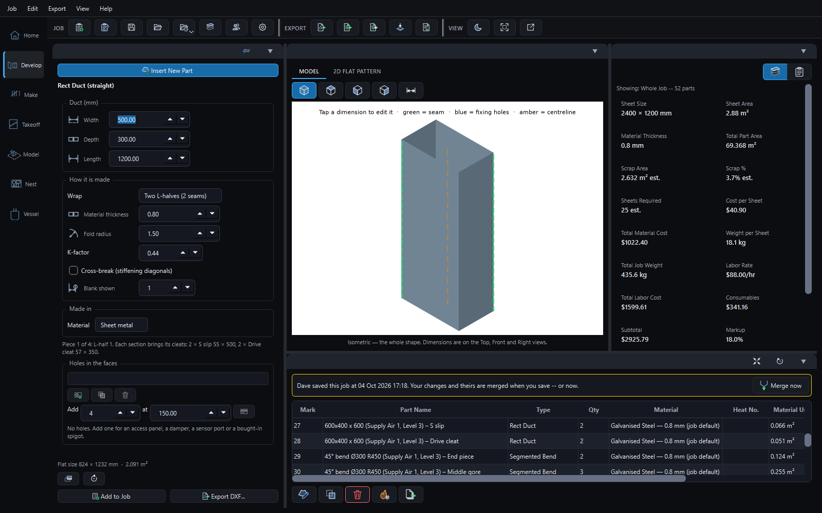
Pittsburgh, snap lock, button punch, standing and grooved seams; one wrap, two L-halves or four panels; slip and drive ends, with the S slips and drive cleats every section needs cut with it.
Specifications by size
Your gauge, seam and connector schedule by duct size and pressure class, suggested for each part as it is added.

Duct board
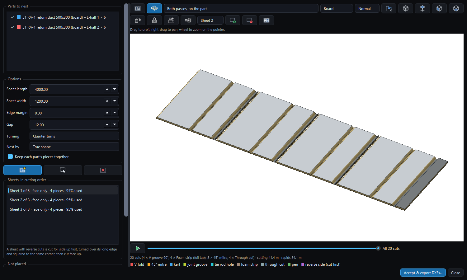
The same duct in board: its panels, grooves and closures from your board's own library, nested onto the board's sheets and shown in 3D as the router will cut them.
Every fitting whole
A tee is its main and its branch, a radius bend its cheeks and its wraps: added to the job together, so the cut list never has half a fitting on it.
Plenums and boots
Cushion heads and boxes closed all round, rectangular or pentagon, with round, rectangular or oval spigots on any face; square and angle boots off a duct.

Model space Add-on New
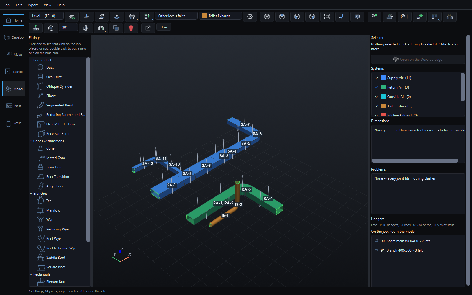
Ductwork in 3D
Runs built piece by piece the way they are installed, set out on levels and grids, and every fitting a numbered part on the job. The whole story →

Built off the open end
The next fitting goes on the blue end, sized to it and turned the way you say: left, right, up or down, with an arrow on the model to show it. Roll it on its end with the ring.

The run follows
A new size goes along the run; a tee dragged along the main stretches the straights either side; a fitting dropped into a straight cuts it.

The job's part numbers
The mark a part has on the job is its label on the model, changed in either place. A drawer shows every part of a kind, placed or still to place.

Systems in colour
Supply, return, outside air and the exhausts, each with its colour and number prefix, and your own added. Hide a system from the legend.
From the consultant's IFC
The model's ductwork placed in 3D where the file has it, on its floors and in its systems, joined and numbered, each fitting made your shop's way.

Over the builder's drawing
The PDF plan laid on the floor at the scale it was measured at on the Takeoff page, lined up by two grid points, and the run built straight over it.

Levels, grids and RLs
Floors with their ceiling and slab, typical floors copied up the building, the grid drawn on the floor, and heights above the floor or as RLs off a site datum.

Position and dimension
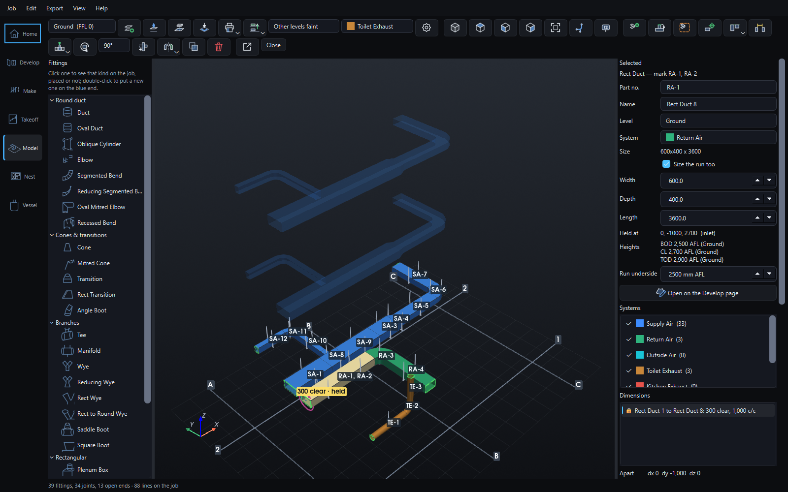
Move to a grid line or set a height; dimension two ducts clear or centre to centre along an axis, type to move, and lock it to hold.
Clashes as you go
Ducts closer than your clearance listed with the overlap and drawn red; ducts out of the ceiling void and joints that do not fit, listed too.
Hangers, measured and priced
Every duct in the void hung at your spacing, on a rod or a trapeze, each rod measured from the slab soffit; rod, anchors, nuts and strut on the quote.

The install drawing
Each floor in plan to a stated scale, with part numbers, sizes, underside heights, the grid and the hangers, and a schedule to match the cut list. One floor or the whole set, as a PDF or a DXF with each system on its own layer.

The model is the job
No export: every fitting is on the job, cut to stock length and developed flat. Open one on the Develop page and the model follows the change.

Plate
Plate and pressure vessels
Rolled, pressed, bevelled, traced to the heat, and checked for pressure.

Rolls or the press brake
For the rolls, the lines to roll to and a pre-bend flat past each seam. For the press brake, the bump lines and their schedule under the form.

Weld prep
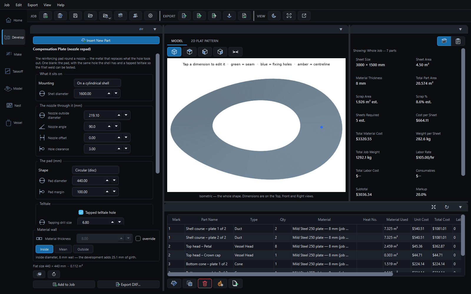
A single or double bevel with its angle and root face, on the seams or every butt edge, opening to the side you choose, on its own layer in the DXF.
Heads, nozzles and pads
Torispherical, ellipsoidal and hemispherical heads in petals round a crown cap, the seams straight or spiral; nozzles through a head, off-centre; compensation plates curved to the shell with a telltale.

Heat numbers
Set once on the parts cut from one plate. The heat goes on the parts table, the cut list, each label and each part's DXF stamp.
Thickness and reinforcement Add-on
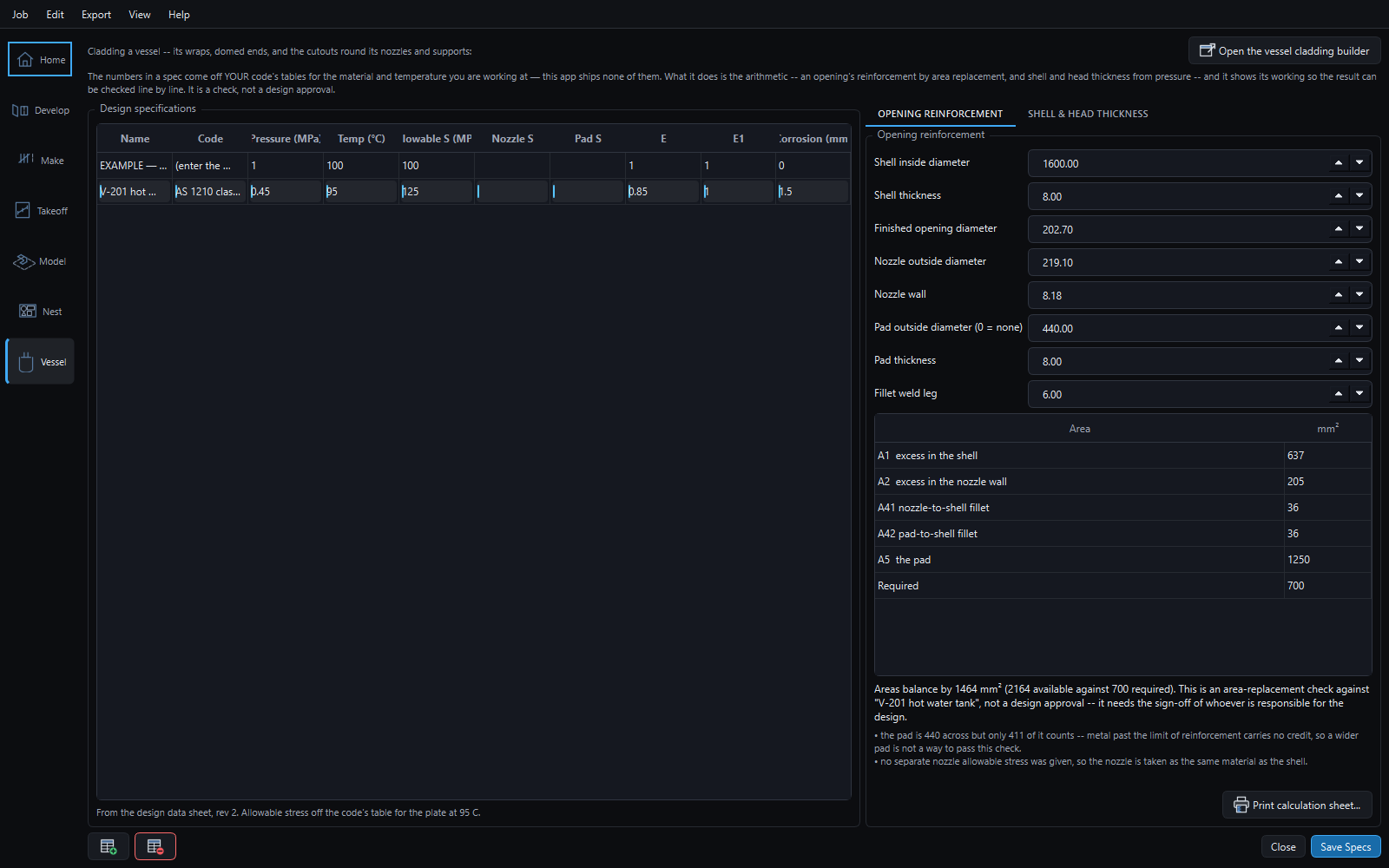
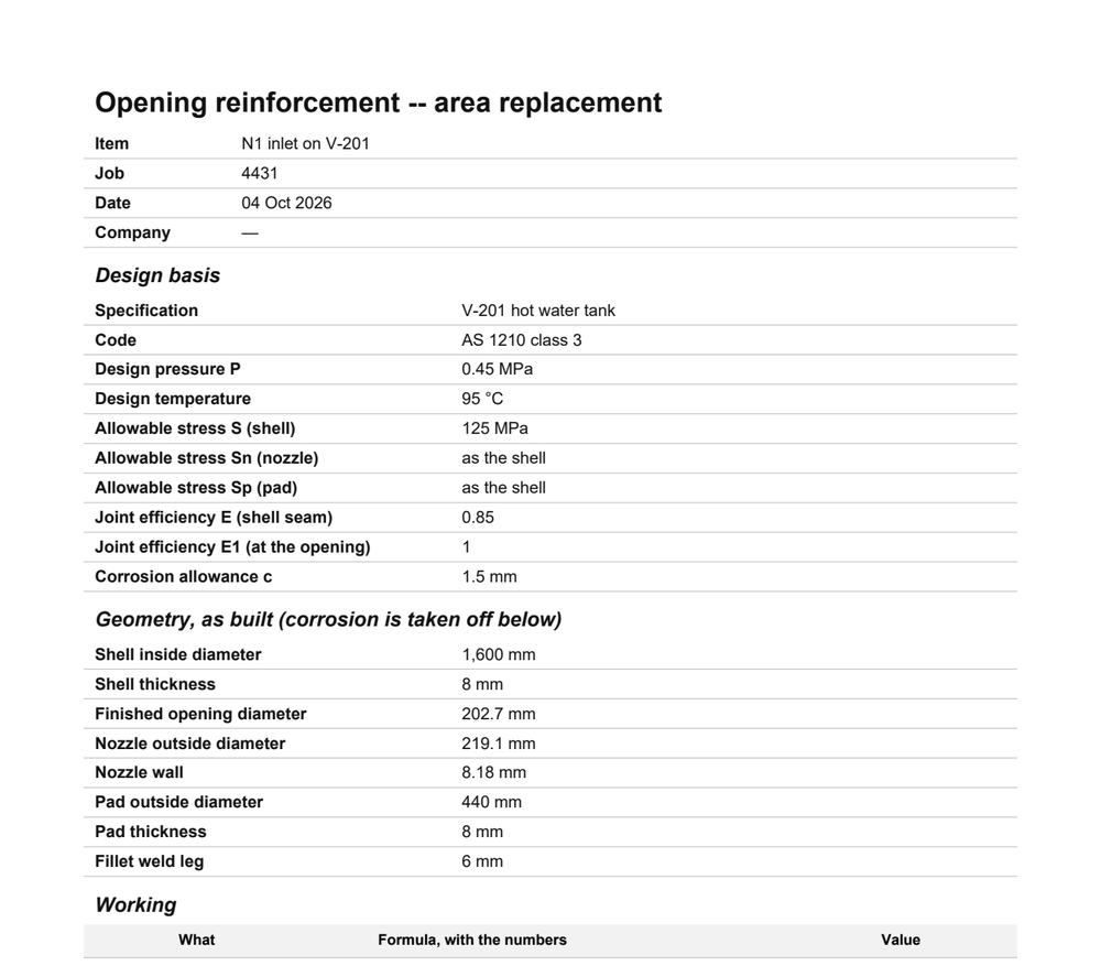
Your own design specs. Shell and head thickness from internal pressure, with the under-tolerance and forming thinning; a nozzle's reinforcement by area replacement. Every line of the working shown.
Calculation sheets
Both checks print with the design basis, the geometry, every formula with its numbers, and a block for calculated, checked and approved.
STEP and STL out
The part as a solid for fit-up checks in your own CAD, built at the plate's thickness, or as an STL.

Takeoff Add-on
Drawings and take-offs
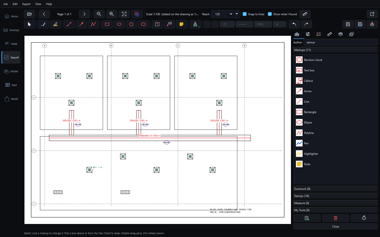
Open the builder's PDF beside the job, measure and count off it, and push what you measured into the job.

It reads the drawing
The scale written in the title block, and the duct and pipe sizes written beside the runs, so a measurement arrives already labelled. It shows what it read.

Count by example
Box one diffuser, name it, and every symbol like it on the sheet is found and counted.

Markups like Revu
Clouds, callouts, text, arrows, stamps and highlights, on layers, with a tool chest of your own. Saved into the PDF with its scale.

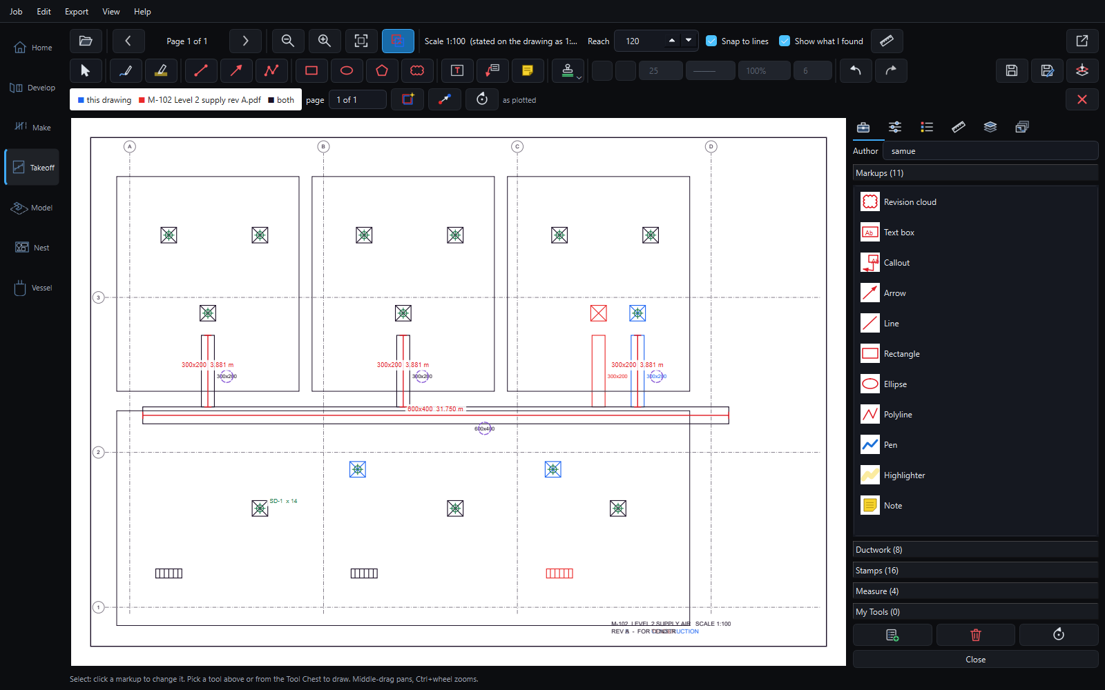
Compare revisions
Lay revision B over A, line them up, and see what moved, what came and what went, in colour.

Sheet sets and their totals
A floor's drawings kept together and in order, each with its own scale and markups, and every measurement added up across the set.
Push to the job
Measured runs become duct at your stock length. Every measurement is listed first with what it would become, or why not.

CSV take-offs
A take-off from another program, in whatever layout your shop already uses, read into the job. In the program itself, no add-on needed.

A second monitor
Pop the drawings out into their own window, with the job open beside them.

Jobs
Jobs, pricing and quotes
One job file holds the parts, the customer, the material and the price, and the office and the floor can both have it open.

Materials and customers
Your materials priced by the square metre or the kilo, with their density for weights, and your customers kept for the next job.
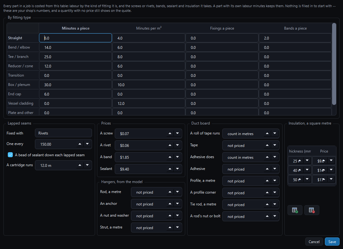
Labour and consumables
Minutes a piece and per square metre by kind of fitting, the fixings, bands, sealant and insulation each takes, priced from one table of your shop's numbers.
A quote on your letterhead
Every line with its material, labour and total, and the markup on top, as a PDF ready to send.

Marks that stay put
Each part's mark is given once and kept, through edits and reordering. Quantities, material and labour edit straight in the table, and everything is undoable.

Shared jobs
Keep the job on the shop's drive. When someone else saves it, a bar says who and when, and their changes merge into yours; where you both changed the same thing, you choose.

Every save kept
The job's history: who saved, on which computer, and what changed. Open an old revision as a copy, or put it back.

The shop
Output for the shop
Paper and files the floor can work from, and the job tracked as it is made.
DXF a cutter can use
Layers you control for cut, bend, seam, bevel, guide and allowance lines; arcs or polylines; mm or inches; your own part stamp. One part or every part at once.
Marking-out sheets
The piece at a stated scale with a scale bar, the measurements you placed on it lettered and listed, and a table of offsets or true lengths to mark it out by hand.

Full-size prints
The piece 1:1 across as many sheets as it takes, overlapped and trimmed so the joins are exact, with a check square on every sheet.
Cut list and labels
Off the same numbers as the quote. A label per piece with its mark, part, blank, heat and a QR code to scan.

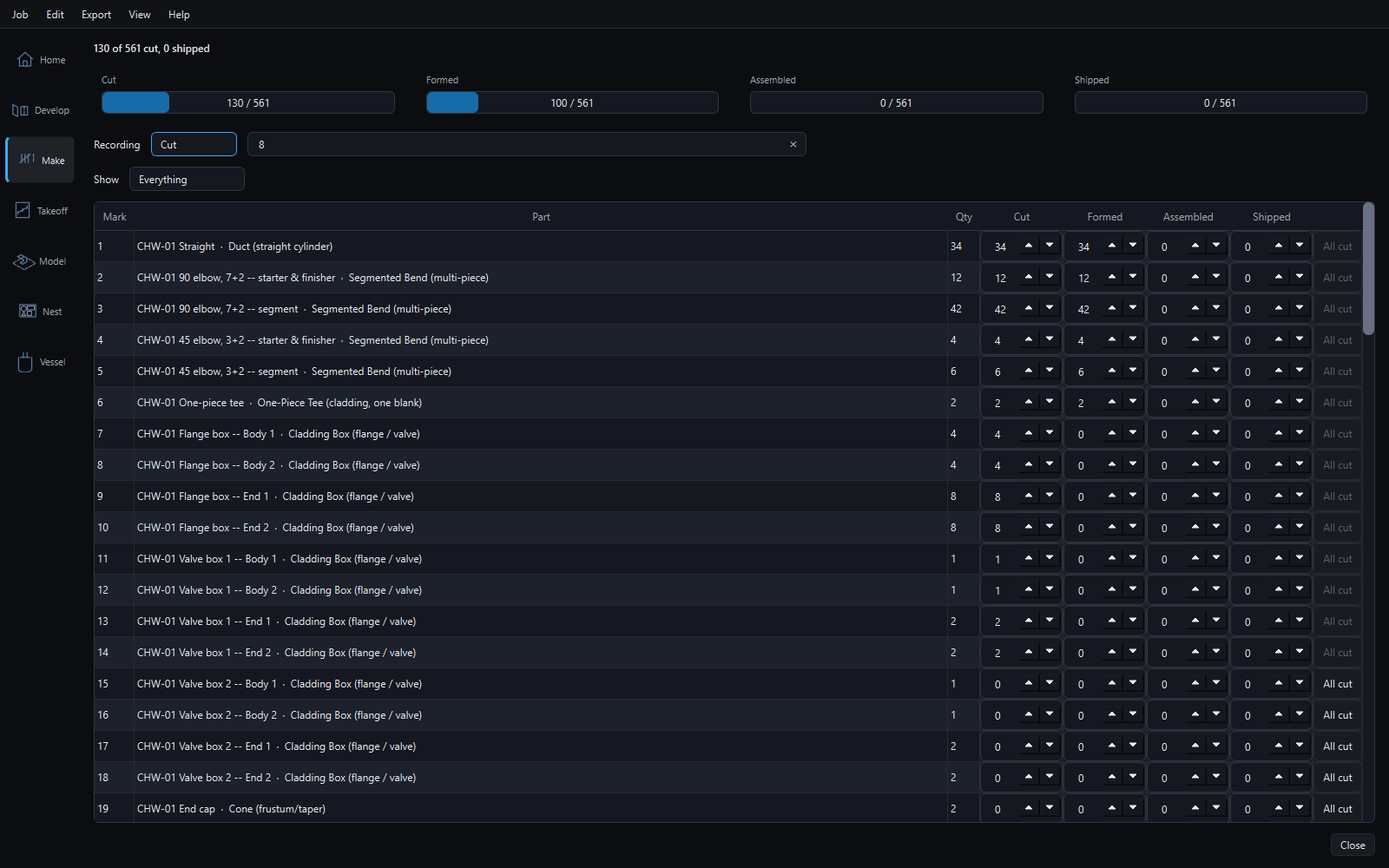
The Make page
How many of each part are cut, formed, assembled and shipped. Scan a label, or type a mark, and the part is counted at that stage.

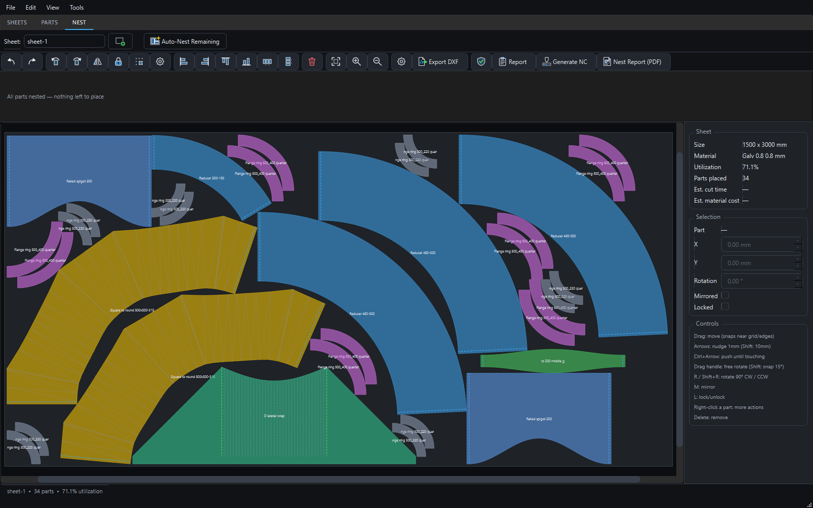
Nesting and CNC Add-on
The job handed over one material at a time; auto-nest onto sheets, plate and offcuts; move and lock by hand; kerf, lead-ins, reports and the program for your table.

The program
The program itself
A Windows desktop program you own, with your jobs on your own disk.

Offline, bought once
A licence tied to the machine, no account and no cloud. Jobs are plain files on your own disk. A 30-day trial with everything in it.
Metric or imperial
Type 3-1/2, 3 1/2 or 3.5 and it reads back in fractions to the nearest 1/16. Everything is kept in millimetres underneath.
A tutorial inside
Help > Tutorial walks four jobs start to finish in the program's own pictures. The same steps are a PDF to read first.

Updates you ask for
Help > Check for Updates says whether there is a newer version. Nothing is downloaded or installed without you.