Beta available now — a 30-day free trial with every add-on included. No card, no account. Start your free trial →
Sheet.Developments

Home / Add-ons / Model space

New Add-on

Model the ductwork.
The job builds itself.

Lay the runs out in 3D the way they will be installed: piece by piece off the open end, on the right floor, in the right system's colour. Every fitting you place is already a part on the job. It wears the number you gave it, it is cut to your stock lengths, and it is developed flat with your shop's seams.
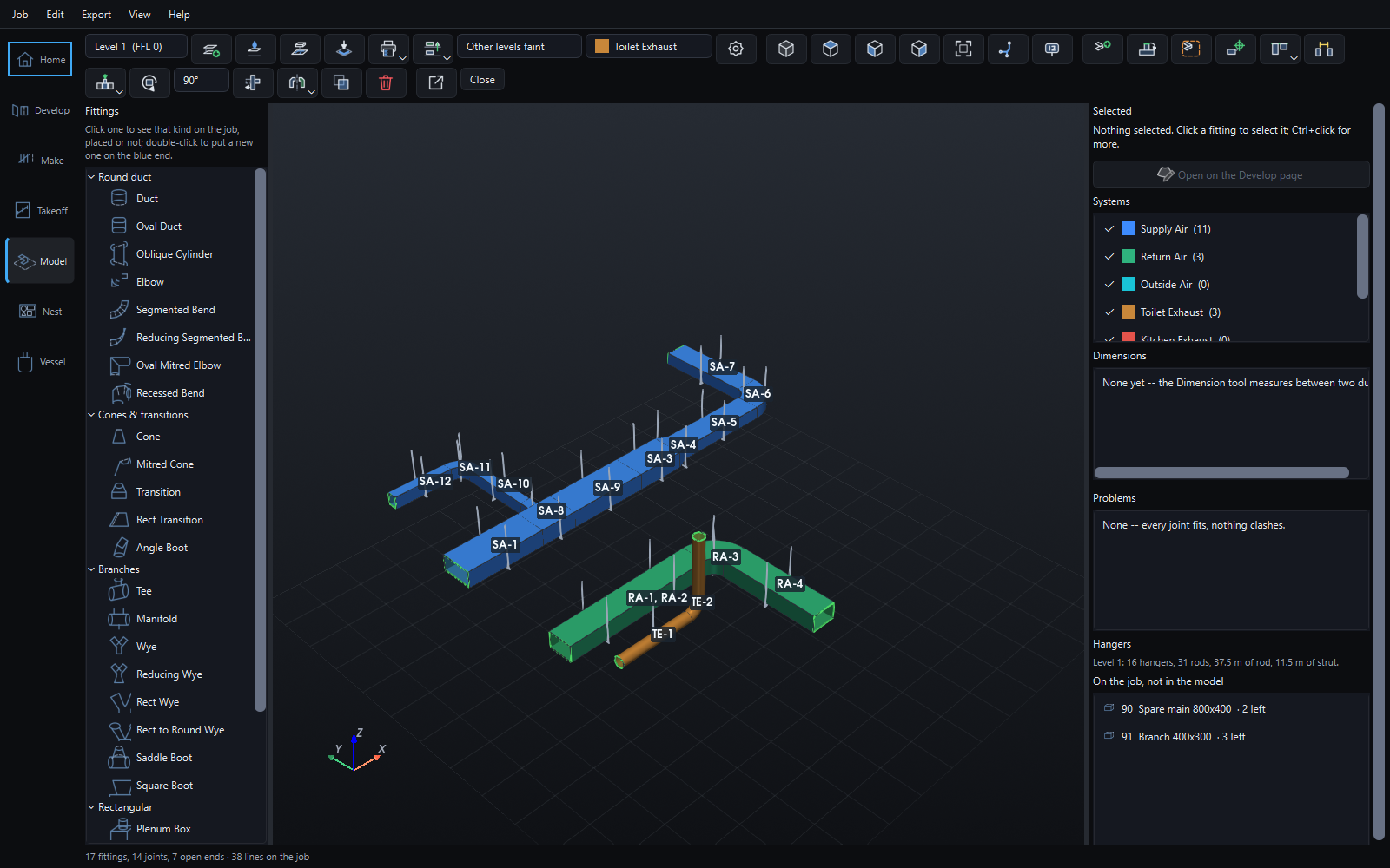
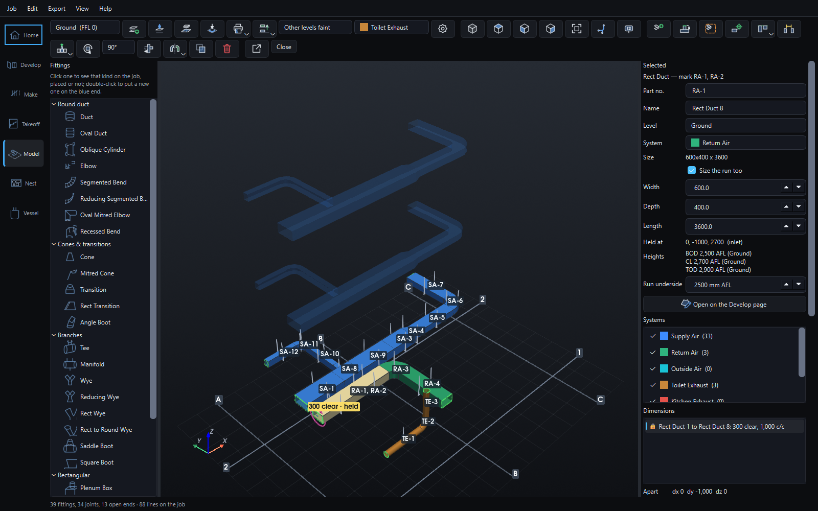
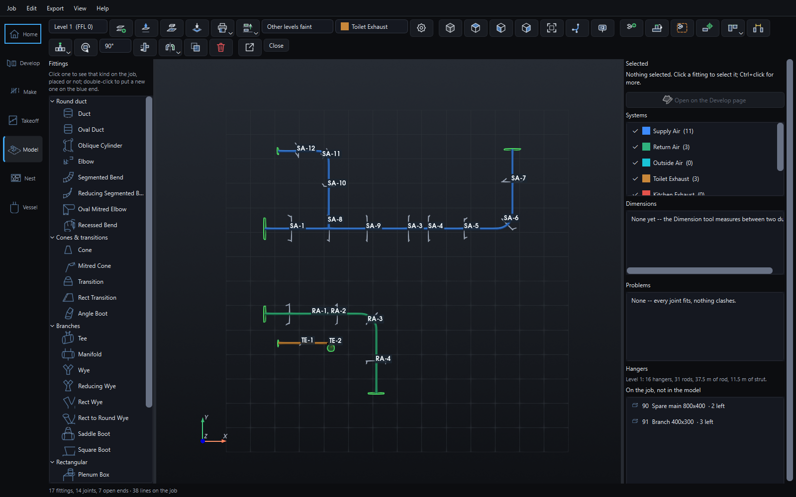
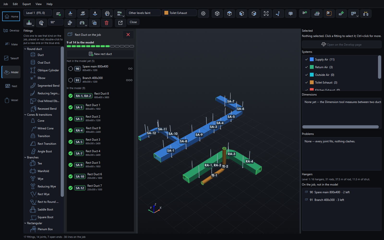
The Model page: a blue supply air main with a tee, a transition and a bend, a green return air run beside it and an orange toilet exhaust riser, every fitting labelled with its part number, the systems listed on the right with their counts, and the problems panel saying every joint fits and nothing clashes
17fittings in three systems 14joints, every one checked 0clashes 38lines on the job, numbered

A supply main with a side-branch tee, a transition and a radius bend; a return run alongside; a toilet exhaust riser. Each in its system's colour, each labelled with the part number the job gives it.
How it works

Four steps from an empty floor to a cut list.

  1. Put the first piece down

    On the level you are working on, at its run height. Then put it exactly where it goes: 1,500 off grid B, underside at RL 103.500.

  2. Build off the open end

    The end you are building from is blue. Double-click the next fitting and it goes on, sized to that end and turned the way you said.

  3. Set it out exactly

    Move a run to a grid line, set its underside, dimension it to the duct beside it and lock the dimension so it stays.

  4. The job is already made

    Every fitting is a line on the job: numbered, cut to stock length, developed flat, priced and on the cut list.

Building

Built the way it goes up.

A fitter thinks in runs: off the end of that duct, a bend to the left, a tee, a transition down to 600 by 300. The Model page works the same way, so a run is laid out in the order it will be installed.

  • Turn it. Left, right, up or down, as you would say it walking along the run. An arrow on the model shows which way the fitting turns, and four buttons change it.
  • Roll it. Grab the ring round its end and roll it. A rectangular bend rolled a quarter becomes its hard-way self on the same hole.
  • Size the run. Change a size and the run follows it: the next duct, the transition, the branch beyond. Untick it to change one fitting alone.
  • Drag along the run. Slide a tee along the main and the straights either side stretch to keep it joined, snapped to your step.
  • Insert into a straight. Drop a tee or a transition into a duct that is already placed, and the duct is cut round it.
  • Copy and mirror. Mirror a run and every fitting swaps to its other hand, so a left tee comes back as a right tee you can actually make.
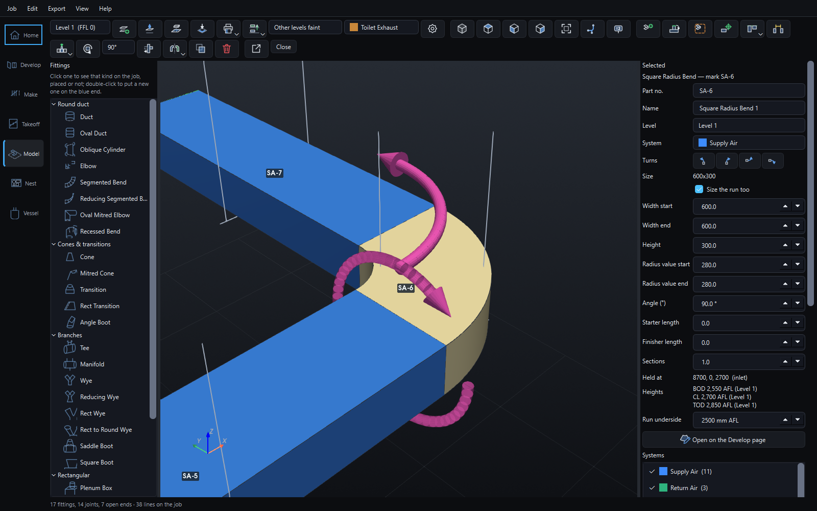
A square radius bend selected in the model, a pink curved arrow showing which way it turns and a ring round its end for rolling it; the side panel shows its part number SA-6, its turn buttons, its sizes and its heights above the floor

SA-6 selected. The arrow is which way it turns and the ring rolls it. Beside it are its part number, its turn buttons, its sizes, and its underside, centreline and top above the floor.

Part numbers

Your numbers, on the model and on the job.

The mark you give a part when you build the job is the label it wears in the model. Change it in either place and it changes in both. A fitting in a system is numbered with that system's prefix, SA-1, SA-2, RA-1, unless you number it yourself.

Click a kind of fitting in the list and a drawer slides out with every one of that kind on the job: a tick for each one in the model, a ring for each still to place, and how many are left. Click one still to place and it goes on the open end; click a placed one and the model shows you where it is.

  • From the take-off. Parts that came in from a take-off or a CSV wait in the drawer to be placed. They keep their size, their mark, their material and their labour. An IFC model can skip the drawer: it goes straight into place.
  • Nothing counted twice. A long straight cut into stock lengths is one fitting in the model and several parts on the job, all under its marks.
The parts drawer slid out beside the model: rect ducts on the job, 9 of 14 in the model shown as a bar of green and empty blocks, parts 90 and 91 listed as not in the model yet with rings, and the placed ones ticked with their marks SA-1, RA-1 and so on

Rect ducts on the job: 9 of 14 in the model. Parts 90 and 91 came in from the take-off and are still to be placed.

Levels, grids and datums

Floors for a tower. A datum for a plant.

Give each floor its level, its ceiling and its slab soffit, and the void between them is where the ducts go. Lay a typical floor out once and copy it up the building. On an industrial site, set the datum and read every height as a reduced level, the way the site's drawings give them.

  • Levels and typical floors. Ground, Level 1 and up, each with its floor level, ceiling and slab. Add a dozen typical floors at a floor-to-floor height in one go.
  • AFL or RL. Heights read above the floor, or as RL 103.400 off the site datum. Bottom, centreline and top, for every fitting you select.
  • The building's grid. Grid lines named and drawn on the floor, to set a run out from.
  • Copy to level. A floor's runs again on the floors above, at the same height above each, numbered as parts of their own.
  • One floor at a time. Show the others faint, hidden or solid while you work.
  • The ceiling void checked. A duct whose underside drops below the ceiling, or whose top runs into the slab, is listed before anyone makes it.
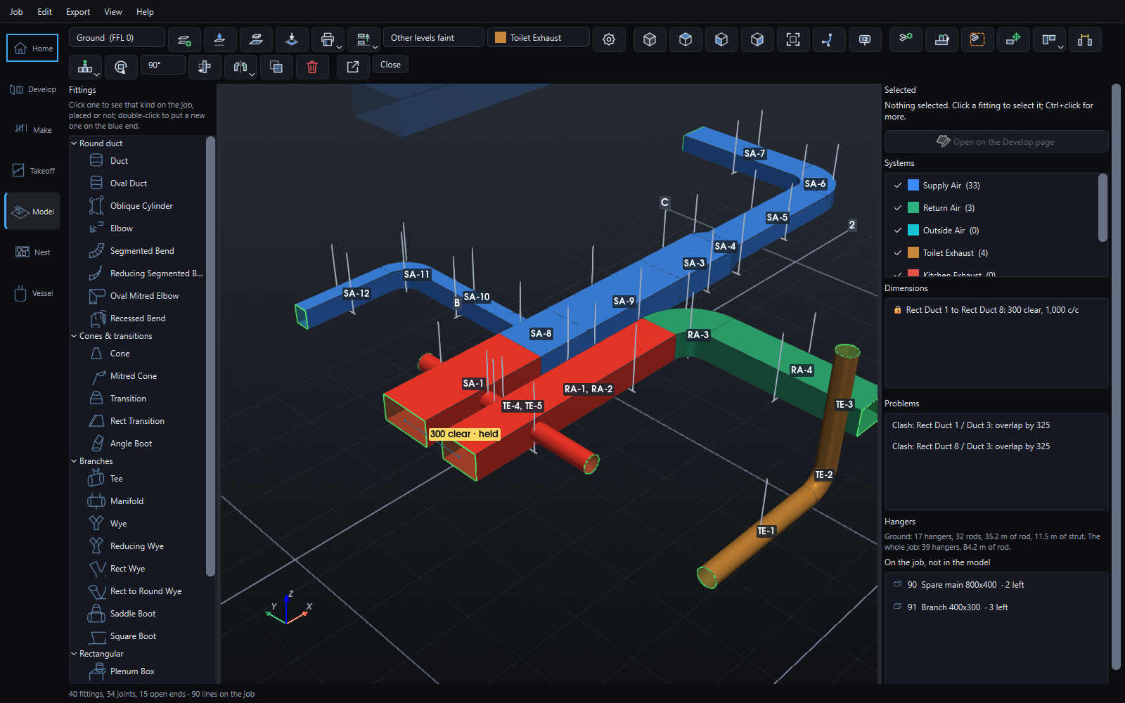
The model with three floors: the ground floor solid and the supply runs copied faintly onto two typical floors above, grid lines A to C and 1 to 2 drawn on the floor with their bubbles, a yellow dimension label reading 300 clear, held, between the return and the supply, and the side panel showing the return's level, system, sizes and its heights above the floor

Ground and two typical floors, with grids A to C and 1 to 2. The supply has been copied up both floors (faint), and the return is held 300 clear of it.

The builder's drawing

Built over the plan, not beside it.

Lay the builder's PDF on the floor and build the ductwork straight over it. A plan you measured on the Takeoff page comes in at the scale you measured it at; one that has no scale yet takes it from the two points you line it up by.

  • Lined up by two points. Click a grid intersection on the drawing and say which one it is, then a second one across the plan. The drawing turns and lands where it belongs.
  • Its scale kept honest. A drawing with a scale keeps it, and you're told how far the second point lands from where you said, so a plan plotted at the wrong size shows up instead of being stretched to fit.
  • Light lines on dark. Shown like a CAD screen, under the floor's grid, at whatever strength you like.
  • A floor at a time. Each level carries its own drawing, and typical floors take a copy of theirs.
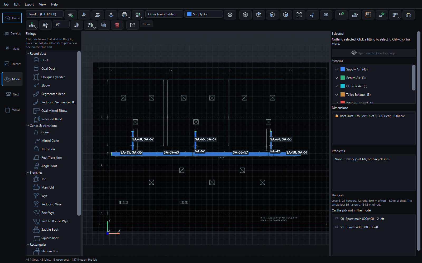
The Model page from above: the builder's supply air plan laid on Level 3 as light lines on dark, and the 600x400 trunk and its three branches modelled exactly over the drawn ones, each labelled with its part numbers

The tutorial's M-102 at 1:100, lined up by its trunk's two ends. The 600×400 trunk and three branches are built over it, and each lands on the line drawn for it.

The consultant's model

An IFC model, placed. Not retyped.

Open the mechanical IFC the consultant sent and choose In the model. Every straight, bend, transition and tee lands where the building model has it, on its own floor, in its own system, joined end to end and numbered. The job's parts are made from it as you watch.

  • Your fittings, not theirs. Each one is made the way your forms make it. Where your bends carry spigots the consultant's don't, the straights either side come out shorter, and every joint still closes on the consultant's lines.
  • Floors and systems by name. A storey becomes the level of the same name, or a new one at its height. Supply Air 1 becomes your Supply Air, in your colour and your numbers.
  • Nothing quietly dropped. Diffusers, dampers and flex are counted, not drawn. A reducing tee or a wye is left for you to make, and the review says which and why.
  • Revit's IFC2x3 or IFC4, in millimetres or feet. One undo takes the lot back out.
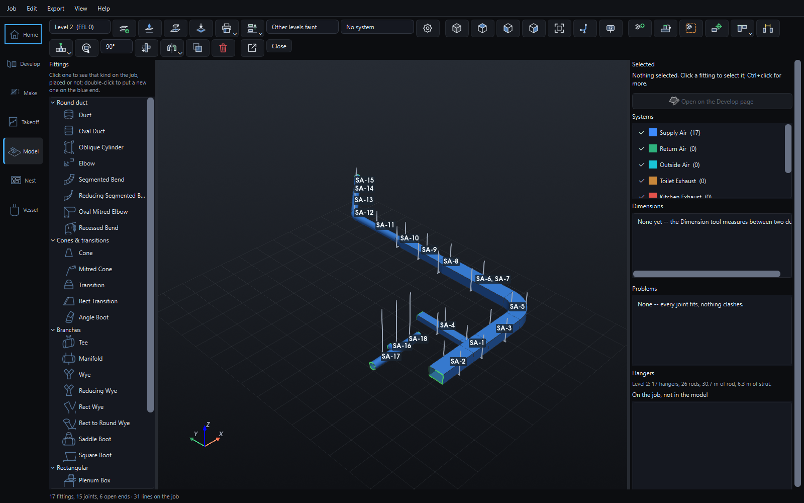
A consultant's supply air system brought in from an IFC model: a 600x400 main with a side branch, a radius bend, transitions to round, a 45 degree bend and a reducer, and a round tee run below, all in the supply air's blue on Level 2, every fitting numbered SA-1 to SA-18 and hung, and the problems panel saying every joint fits

From the file to the floor in one step. Seventeen fittings placed, joined and numbered. The two straights beside the shop's spigotted bend were cut to suit.

Setting out

Set out to the millimetre, and kept there.

Pick one fitting or a whole run and put it where the drawing says it goes. Then dimension it to its neighbour, and lock it.

  • Position. Move by a distance; move to a point measured from the origin or from a grid line; or set the height by its bottom, centreline or top, above the floor or as an RL.
  • Align. Line a run's bottom, centreline or top up with another run's.
  • Dimension. Click two ducts. Read the clear gap or centre to centre, north–south, east–west, up and down, or straight between them. Type a new distance and the second run moves to it.
  • Lock it. A locked dimension holds. Widen the supply main and the return beside it steps over to stay 300 clear. Drop the return's underside and it stays 300 clear sideways, because the dimension knows which way it measures.
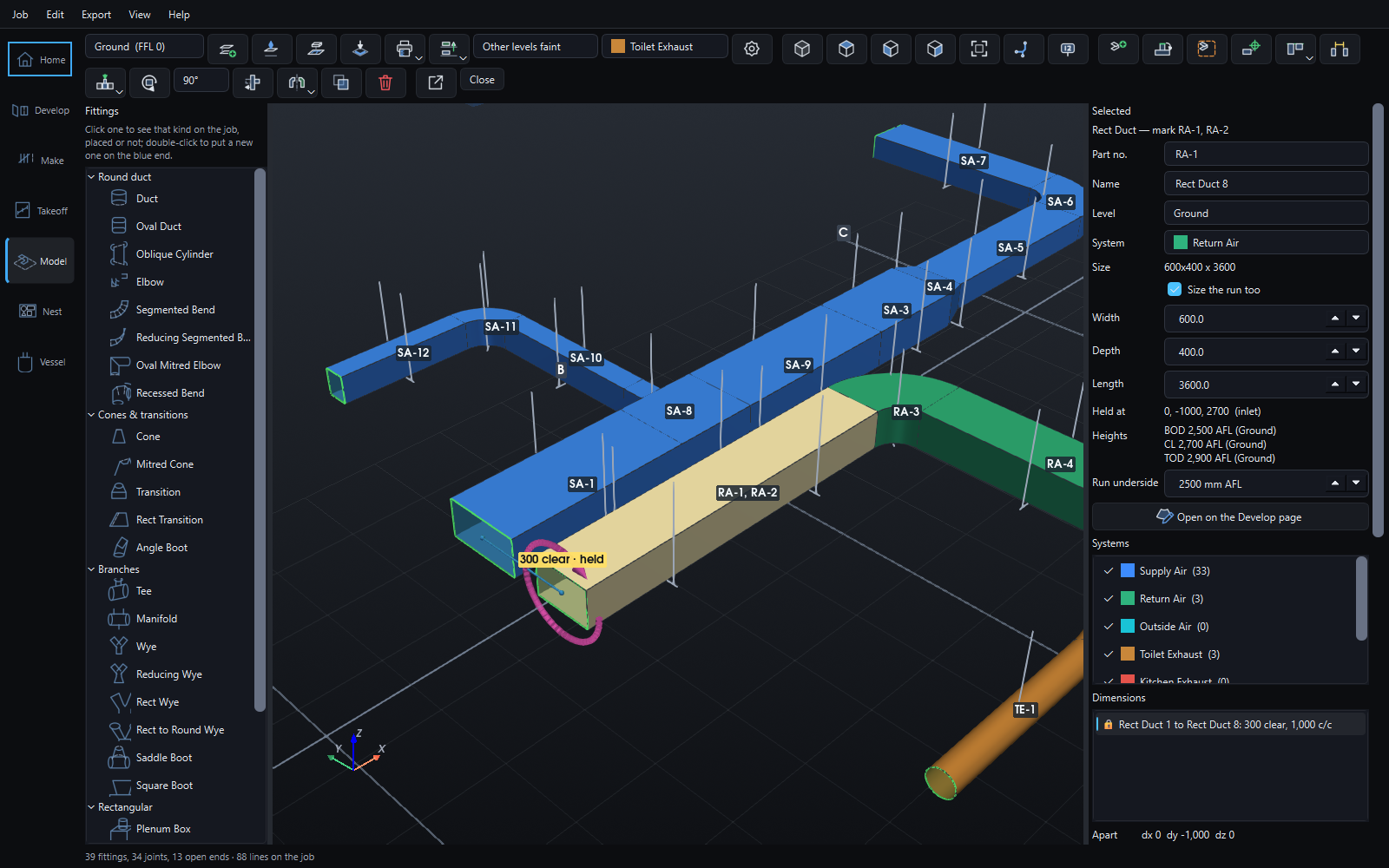
Close up of the return air duct selected beside the supply main, a yellow label reading 300 clear, held, and the dimensions list showing Rect Duct 1 to Rect Duct 8, 300 clear, 1,000 centre to centre, locked, measured north-south

300 clear, held. The dimension measures north–south, the way it was drawn, so changing a height never drags the run sideways.

Clashes

Clashes found while you draw, not on site.

Any two ducts closer than your clearance are listed with how much they overlap, and drawn red until they are moved. The clearance is yours to set, because insulation, flanges and hangers all need room. Ducts joined to each other are left alone, and so are two that meet end to end; a mismatched joint is a problem of its own and is reported as one.

  • Every joint checked. Two ends that meet but are not the same size, shape or way round are listed by name.
  • Nothing silent. A held dimension that cannot be kept, or a duct out of its void, is in the same list.
A 250 round exhaust duct drawn straight through the return and the supply main; all three are drawn red, and the problems panel lists two clashes, each an overlap of 325

An exhaust run drawn straight through the return and the supply. Overlap by 325: the distance it has to rise to clear them.

Systems and views

Every system in its own colour.

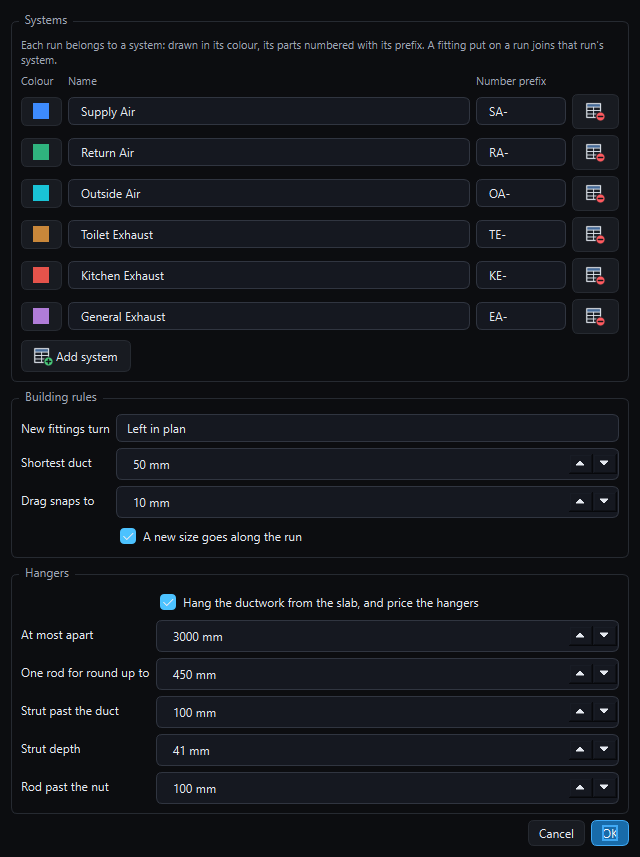
Supply, return, outside air, toilet, kitchen and general exhaust to start with, each with a colour and a part-number prefix. Add your own. A fitting put on a run joins that run's system, and ticking a system off the legend hides it.

The model settings: six systems with their colours and number prefixes, supply air SA, return air RA, outside air OA, toilet exhaust TE, kitchen exhaust KE and general exhaust EA, and the building rules: new fittings turn left in plan, shortest duct 50 mm, drag snaps to 10 mm, a new size goes along the run

Systems, the building rules and the hangers: which way a new fitting turns, the shortest duct, the drag step; how far apart hangers go, when a round duct takes one rod, the strut and the thread.

The model from above as single lines in each system's colour, labelled with part numbers, for checking the layout against the drawings

Single lines from above, labelled, to check the layout against the drawing at a glance.

The model is the job

No export. No second copy.

There is nothing to send from the model to the job, because they are the same thing. Every fitting is a line on the job, and a long straight is cut into your stock lengths. Each one is developed flat with your shop's seams, priced with the rest, and printed on the cut list and the labels.

Open a fitting on the Develop page and change it there; the model follows, and so does the run beyond it. Save the job and the model goes with it. Undo works on all of it.

  • Your shop's construction. A new fitting starts from the form you have set for that shape on the Develop page: Pittsburgh or snap lock, one wrap or two L-halves, slips and drives, with the job's thickness.
  • Hung from the slab, and priced. Every duct in the ceiling void is hung at your spacing, on one rod or a trapeze, each rod measured from the floor's slab soffit. The rod, anchors, nuts and strut go on the quote.
  • Then the shop. Nest the parts, write the program for the table, and track every one on the Make page as it is cut.
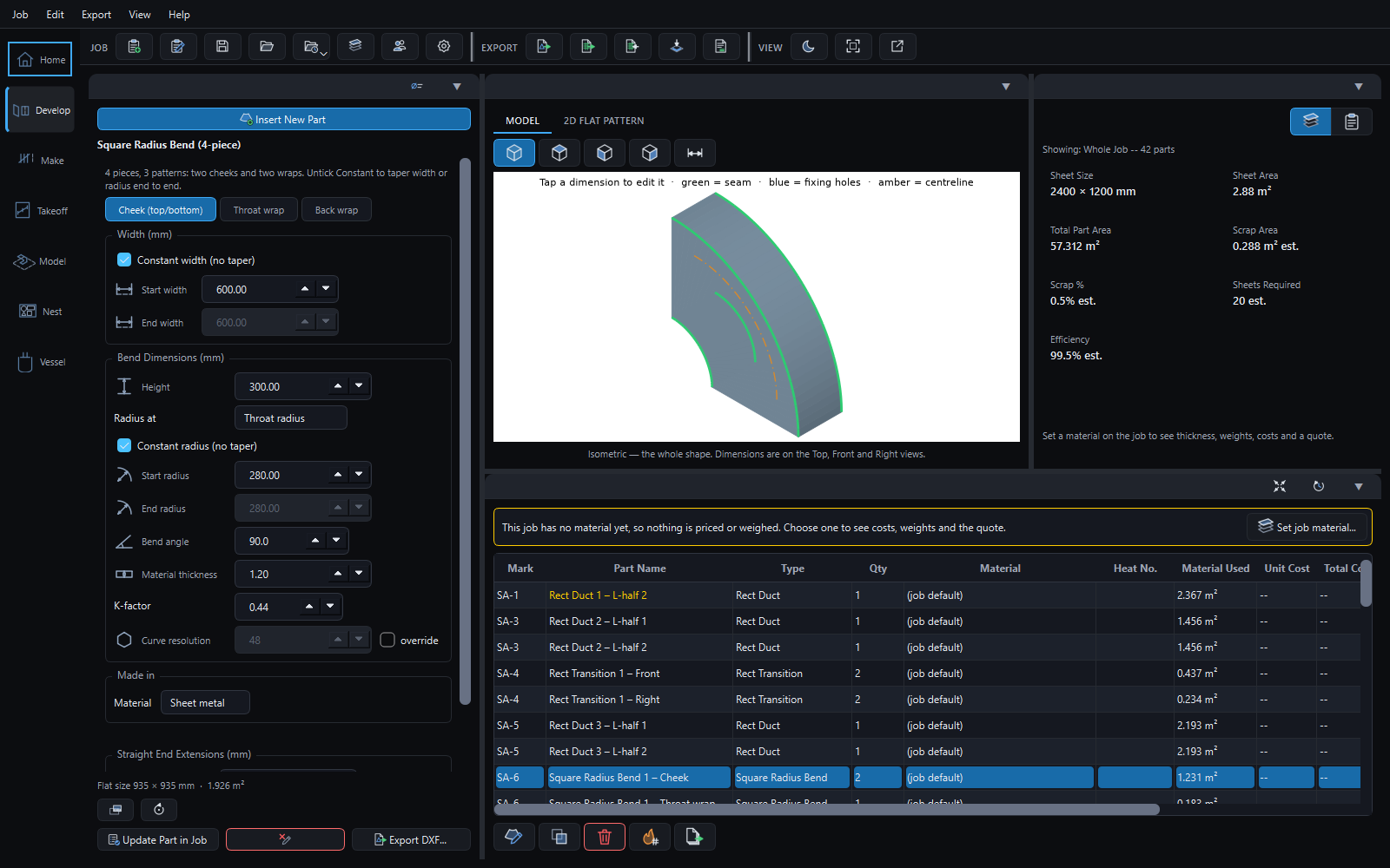
The Develop page with the square radius bend SA-6 open from the model: its sizes on the left, the bend in 3D in the middle, the job's sheet use on the right, and the job's parts below with their marks SA-1, SA-3, SA-4, SA-5 and SA-6 highlighted

SA-6, opened from the model. The square radius bend's cheeks and wraps are on the job under its mark, with the job's sheet use worked out beside it.

The install drawing

Every floor on paper, to scale, for the installers.

Print layout turns a floor, or every floor as one set, into the drawing the install crew works from: the ductwork in plan at a stated scale with every part number, size and underside height, the grid, the held dimensions and every hanger. Then a schedule listing the same parts by the same marks as the cut list. And the same layout goes out as a DXF in real millimetres, each system on its own layer, for the services coordinator's model.

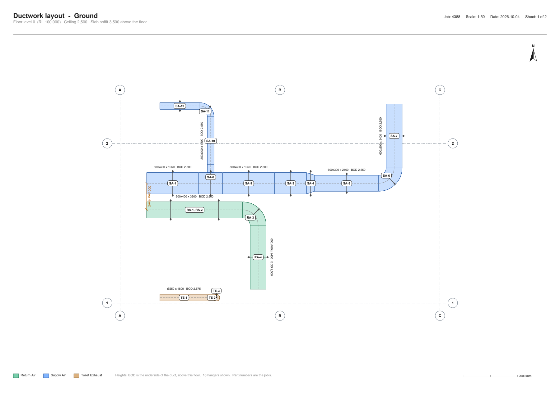
A printed ductwork layout of the ground floor at 1:50: the supply, return and exhaust runs in plan in their systems' colours, every fitting's part number in a bubble, sizes and underside heights along the straights, the grid with its bubbles, hanger struts and rods, a north arrow, the legend and a scale bar

The ground floor at 1:50 on A3, drawn straight from the model: no export, no redrawing.

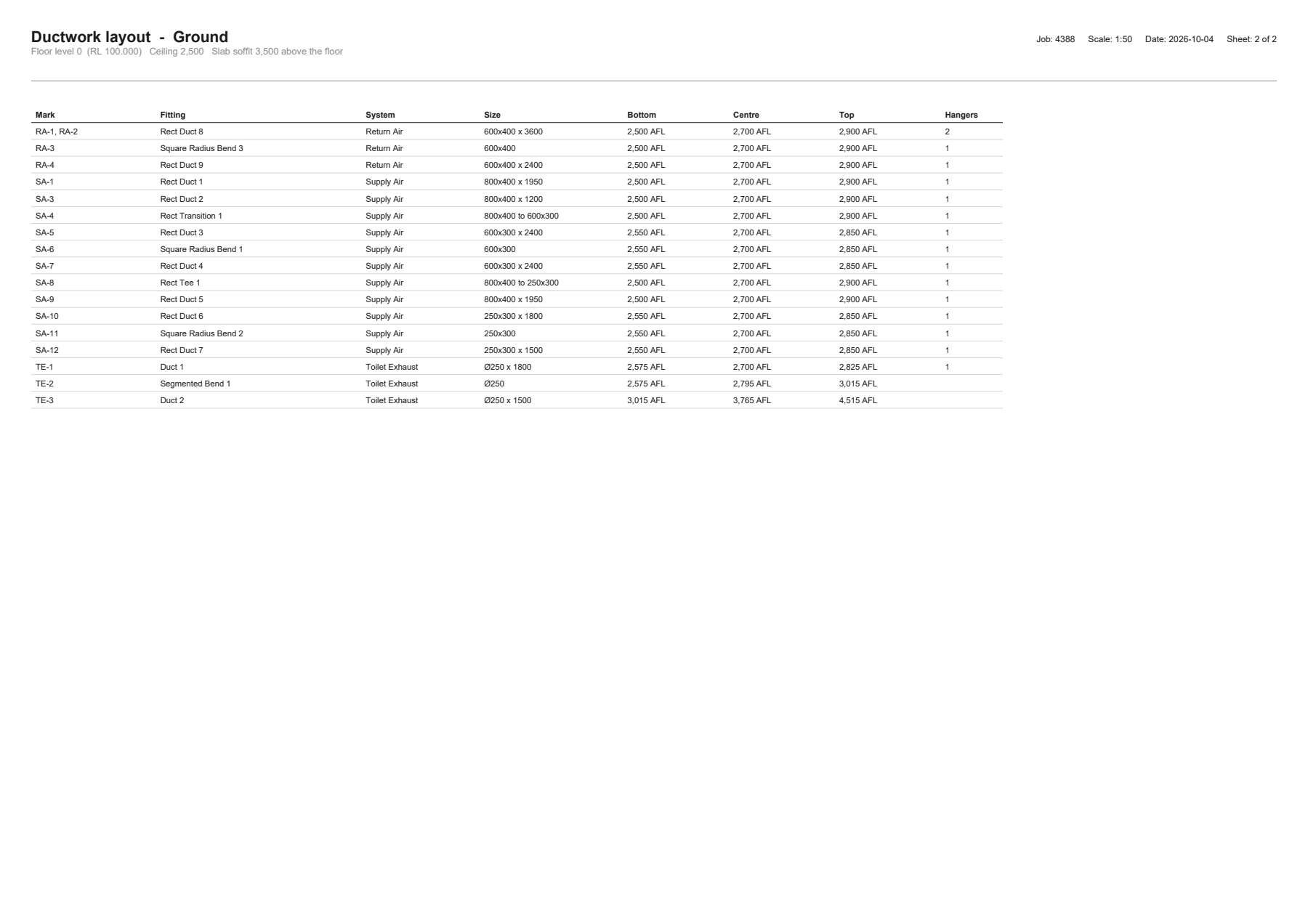
The schedule sheet: every fitting on the floor with its mark, fitting, system, size, and bottom, centre and top heights above the floor, and how many hangers it takes

And its schedule: mark, size, and bottom, centre and top heights for every fitting on the floor.

On the toolbar

The Model page's tools.

Each one below is shown with the icon of the button that does it in the program. Hover any button there and it says what it does.

New run

The next fitting starts a run of its own on the level you are on, ready to be positioned.

Insert a fitting

A tee, a transition or a bend dropped into a straight that is already placed.

Size the run

A new size goes along the run, so the next fitting and the one after it still fit.

Turn

Left, right, up or down, walking along the run, with an arrow on the model to show it.

Roll

Round the end it hangs from, by the step you choose, with everything beyond it.

Mirror copy

The run mirrored, each fitting swapped to its other hand so it can be made.

Select the run

Everything joined to the fitting you picked, to move, copy or set out as one.

Position

Move by, move to a point or a grid line, or set a height, above the floor or as an RL.

Align

Bottoms, centrelines or tops lined up with another run.

Dimension

Clear or centre to centre, along an axis, typed to move and locked to hold.

Levels and grid

Every floor's level, ceiling and slab, typical floors, the site datum and the grid lines.

Drawing under the floor

The builder's PDF on the level, at its scale, lined up by two grid points.

Import IFC model

The consultant's ductwork placed in 3D on its floors and systems, joined, and made your shop's way.

Copy to level

The selection again on other floors, at the same height above each.

Print layout

The install drawing and schedule for a floor, or every floor as one set.

Systems

Colours, prefixes and the building rules, in Model settings.

Single line

The layout as labelled centrelines, for checking against the drawing.

Part numbers

Every fitting's marks on the model, or none, for a clean picture.

Why it is built this way

Made for the shop that makes the duct.

Most 3D duct software is drawing-office software: the model is the product, and getting parts out of it for the shop is an export, a translation and a check. Here the parts were the product from the start.

Model spaceHow it is usually done
Getting parts outThere is no step. Each fitting is a part on the job, developed flat, as it is placed.Export the model, import it into the fabrication program, check nothing was lost.
Part numbersThe job's marks, shown on the model, the same in both places.Numbers made at export, matched to the drawing by hand.
Setting outDimensions between ducts that hold when the runs change, along the axis they measure.Measure, move, and measure again after every change.
The builder's drawingLaid on the floor at the scale it was measured at, lined up by two grid points, and the miss reported.Imported as a background and scaled by hand until it looks right.
High-rise and industrialLevels with ceiling voids, typical floors copied up, grids, and RLs off a site datum.Often a separate model per floor, or a site datum worked out by hand.
Install drawingsEach floor printed in plan to a stated scale, with part numbers, sizes, heights, grid and hangers, and a schedule.Exported to CAD and dressed up by hand, or drawn again.
HangersWorked out from the slab soffit for every duct, drawn on the model, counted and priced on the quote.Placed one by one, or counted off the drawing by hand.
ClashesFound as you draw, with the overlap, against a clearance you set.A separate check, run when the model is finished.
Owning itAn add-on to a program bought once, on your machine, offline. Jobs are plain files.A subscription and an account, often a server or a dongle.

In the beta now

Model your next job, free for 30 days.

Model space is in the trial, with every other add-on. No card, no account.