Beta available now — a 30-day free trial with every add-on included. No card, no account. Start your free trial →
Sheet.Developments

Screenshots

What it actually looks like

Shots from the current build: not mock-ups, not a designer's impression. Every number in them came out of the software. Click any image to see it full size, or read the tutorial for three whole jobs a step at a time.

The way in

Pick a shape and start

Forty-seven shapes, grouped the way a shop thinks about them rather than alphabetically. Quick Design is one part straight to a DXF with no job around it; New Job adds the parts list, materials and costing when you need to quote.
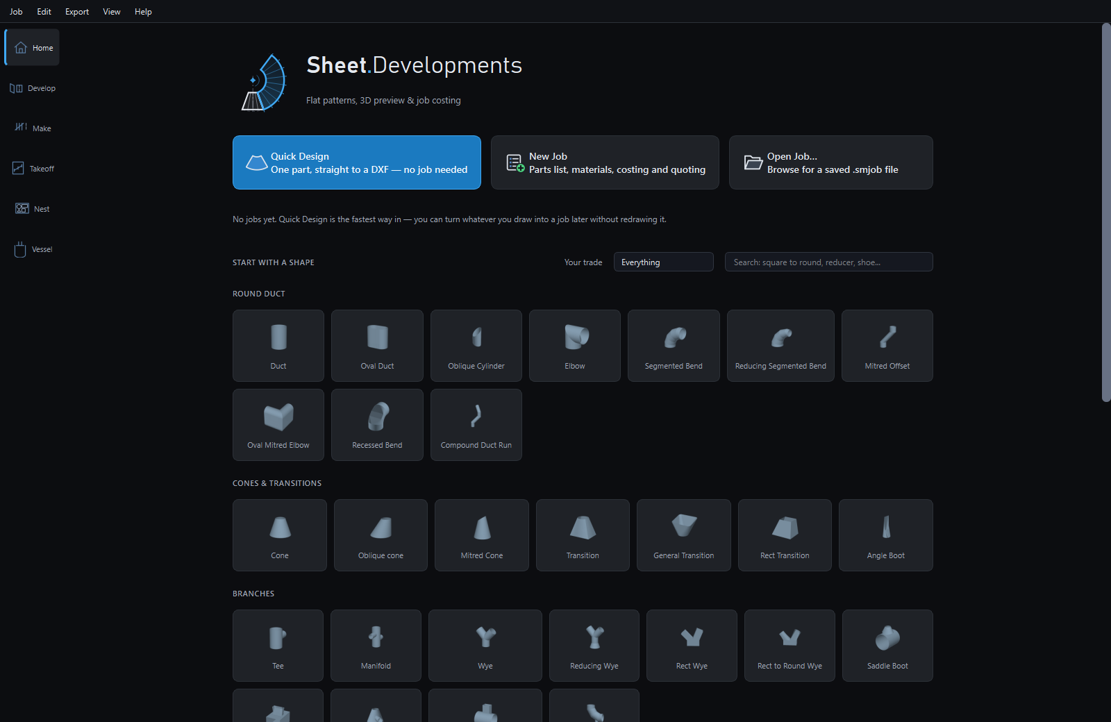
The Sheet.Developments start screen, showing Quick Design, New Job and Open Job, with the shape library below grouped into Round Duct, Cones and Transitions, Branches and Rectangular

Anything you draw in Quick Design can be turned into a job later without redrawing it.
The development

A cone, with the wall thickness already in it

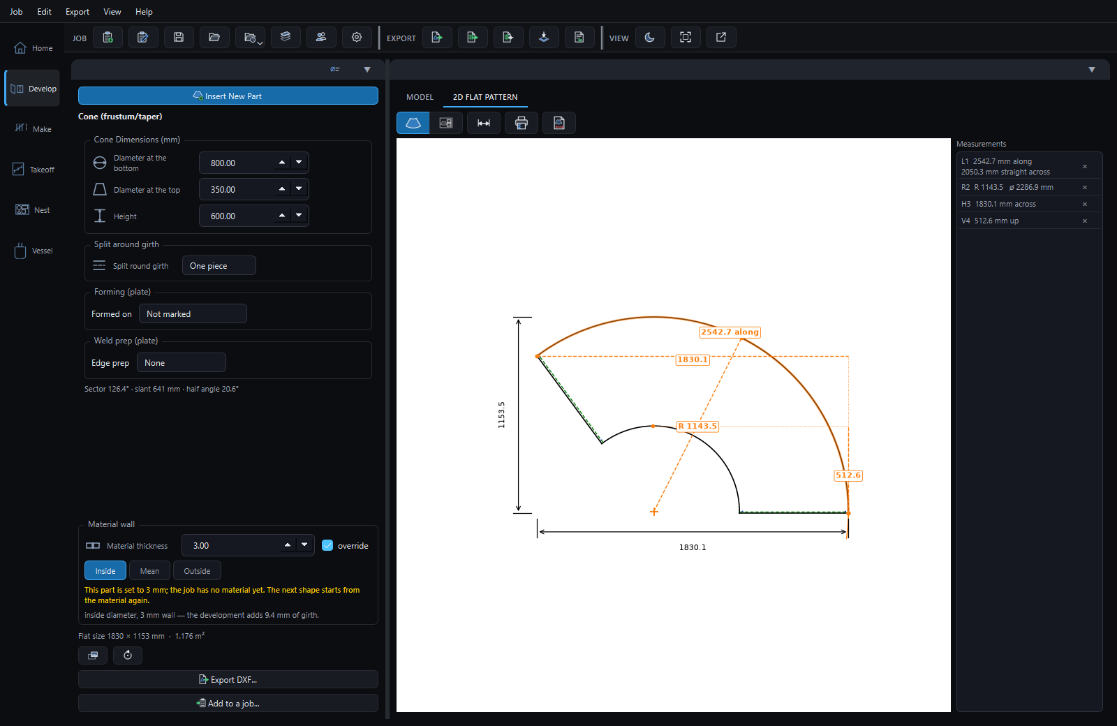
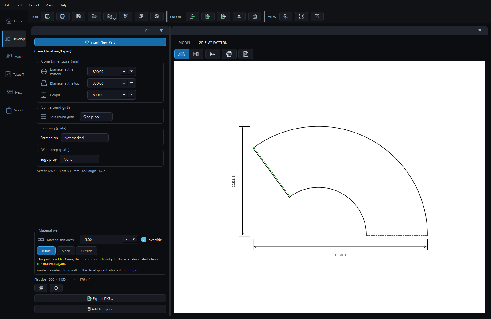
An 800 to 350 cone, 600 high, in 3 mm plate. The diameters were typed as inside diameters, so the pattern develops on the middle of the material and the girth comes out 9.4 mm longer than the bare numbers would give. Seam laps are drawn in green, on their own DXF layer.

A cone development on screen: dimensions panel on the left showing 800, 350 and 600 with a 3 mm wall on an inside-diameter basis, the flat pattern in the middle with its overall size dimensioned
Flat size 1830 × 1153 mm Girth added by the wall 9.4 mm Splits to fit when it won't fit the sheet

Before you cut

See the part, not just the blank

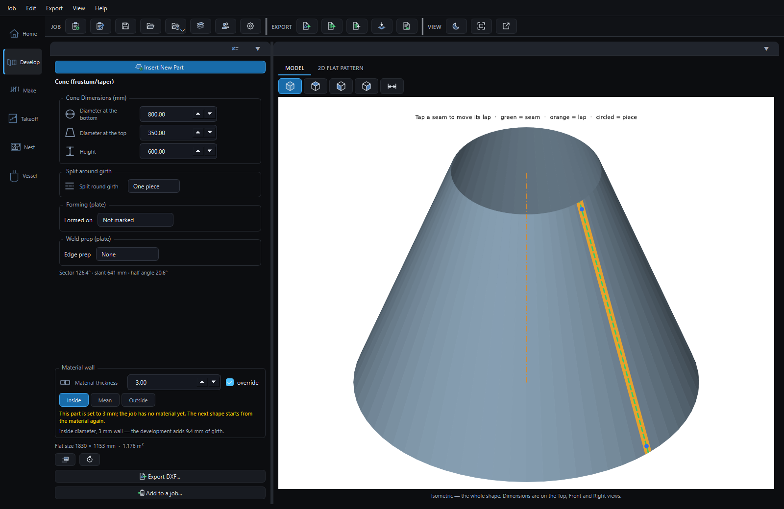
The same cone as a model, from iso, the top, the front or the side. The seam is green and any fixing holes are blue, so you can see where the joint lands before the plate is on the machine — which is the cheapest time to notice it is in the wrong place. Tap a dimension on the model to change it.

The model tab showing the cone shaded and rolled up in an isometric view, with the seam marked as a green dashed line down its side and the axis in amber

Checking

Measure anything on the pattern

Eight kinds of measurement, and the picks snap to ends, centres, midpoints, quadrants and intersections. Along curve runs the tape around the arc rather than straight across it — between the same two points on this cone that is the difference between 2050 mm and 2543 mm. Every measurement stays on the drawing and comes out on the marking-out sheet.

The flat pattern with four measurements marked on it in orange: a length along the outer arc, a radius, a horizontal size across the blank and a vertical size, with the values listed in a panel beside the drawing
Along the arc 2542.7 mm Straight across the same two points 2050.3 mm Radius R 1143.5

The detail most software gets lazy about

Inside, mean or outside — say which

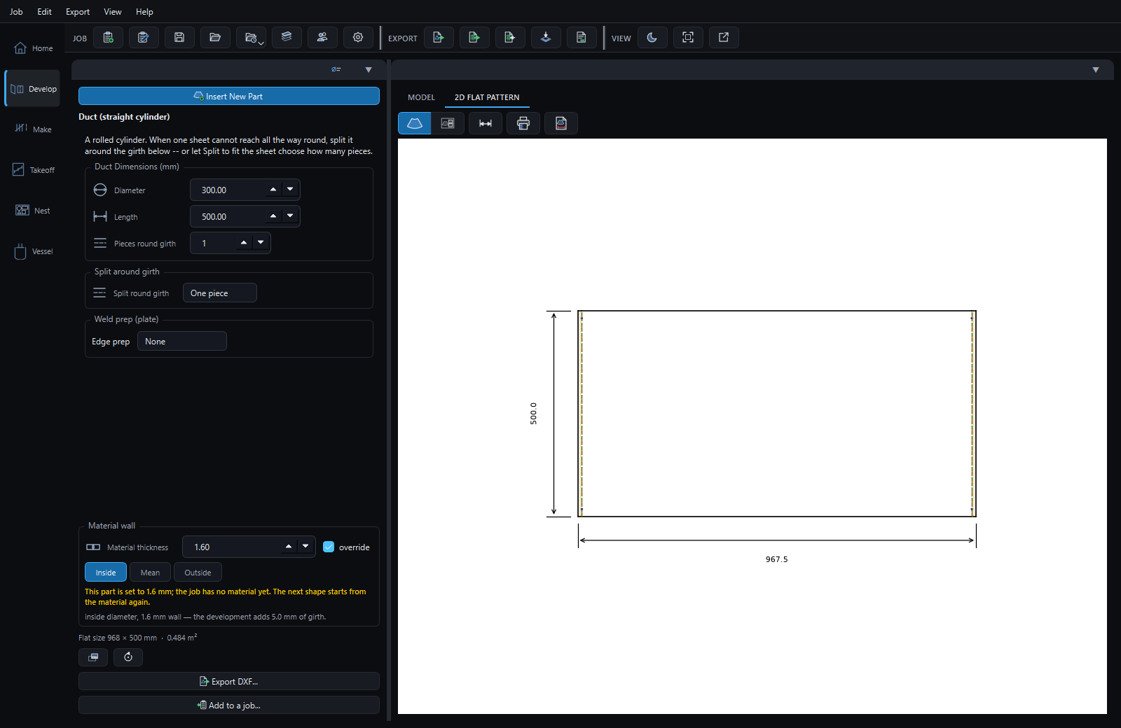
A 300 duct in 1.6 mm. If 300 is the inside diameter, the blank is not π×300. It is π×301.6, because the material rolls about its middle — 5 mm of girth, which is a 5 mm gap or a 5 mm overlap at the seam. Set it per part; the software says in plain words what it did.

A straight duct pattern with the Material wall panel showing a 1.6 mm wall on an inside-diameter basis and the note: inside diameter, 1.6 mm wall, the development adds 5.0 mm of girth
Typed 300 inside Develops on 301.6 Blank 968 × 500 mm

The general transition

Any two ends, each in its own plane

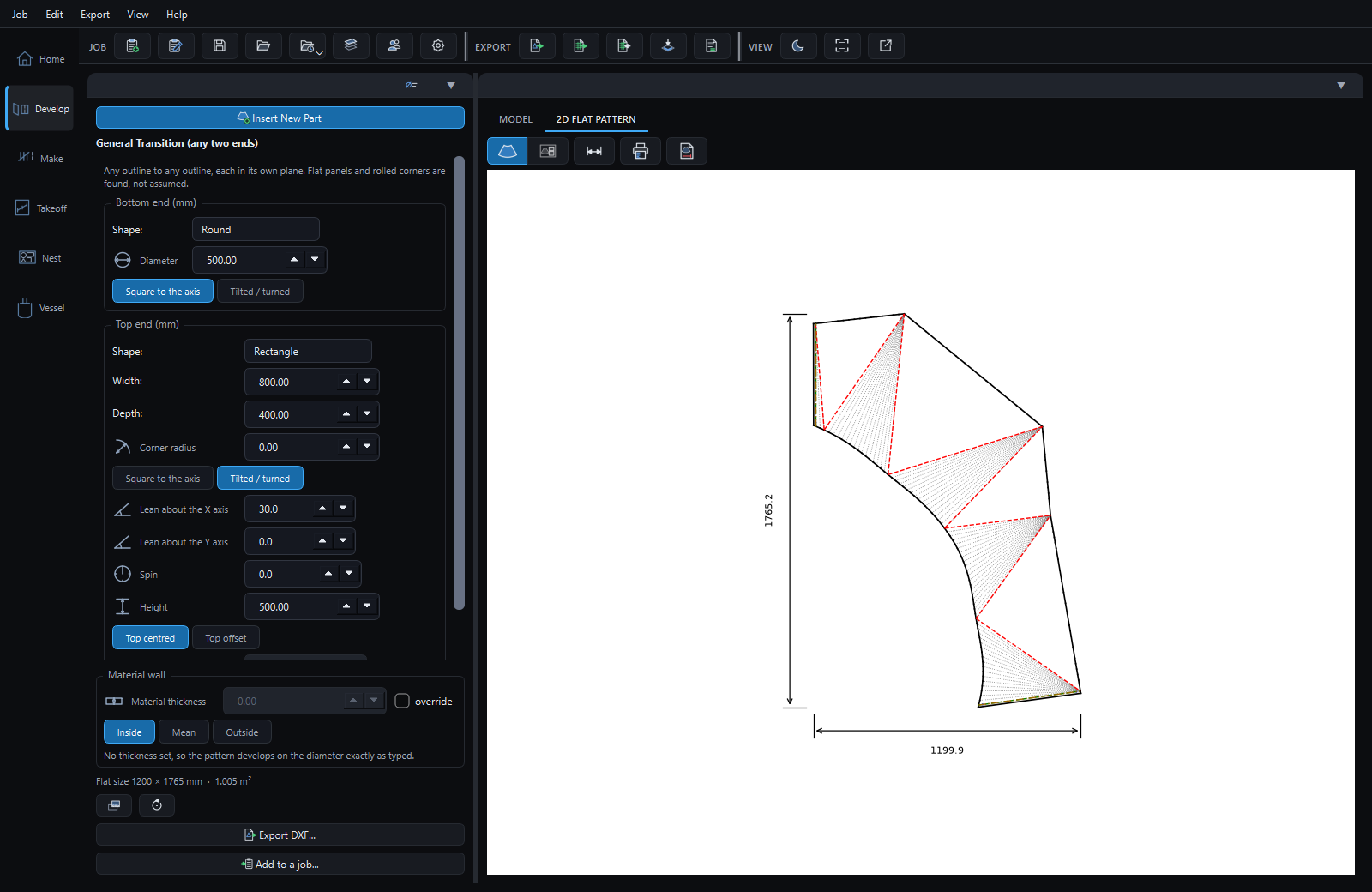
Round 500 at the bottom, an 800 × 400 rectangle on top leaning 30°. Each end can be round, a rectangle with a corner radius, a flat oval, a polygon or your own corner points, and either can lean and turn. The straight sides come out as flat triangles, the corners as cones, and the red lines are where the rolling starts.

The general transition form with a round bottom and a rectangular top tilted 30 degrees, and its development: flat triangles, rolled corners, and red lines where rolling starts
Flat size 1199 × 1770 mm Top leaning 30° Lines where rolling starts 8

Cladding

Pipe sizes by the standard, and the cladding round them

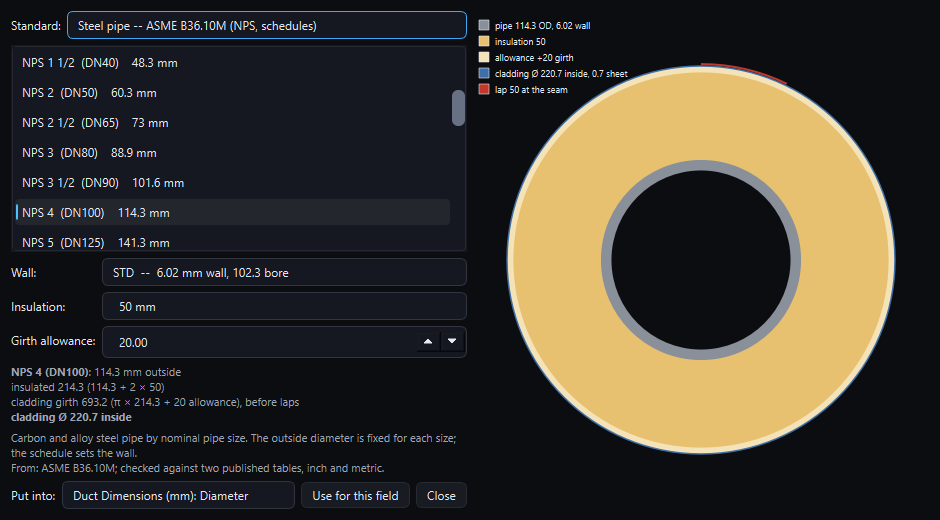
NPS 4 steel pipe, 50 mm of rockwool, and the 20 mm of girth this shop adds because rockwool is never quite its nominal thickness. The drawing is end on and to scale: pipe wall, insulation, the allowance, the cladding, and the lap at the seam. Use for this field puts the answer into the fitting.

The pipe and tube sizes window with ASME B36.10M NPS 4 selected, standard wall, 50 mm insulation and 20 mm girth allowance, beside an end-on drawing of the insulated pipe and its cladding
NPS 4 114.3 OD Insulated 214.3 Cladding Ø 220.7 inside

Cladding

A tee from one blank

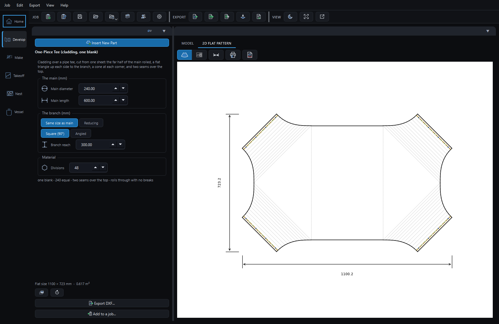
The lagger's one-piece tee: the far half of the main rolled, a flat triangle up each side to the branch, a cone at every corner, and two seams over the top — here with four fixing holes down each seam edge.

A one-piece cladding tee, 240 equal, developed as a single blank with fixing holes along its seams
240 equal tee 1100 × 723 mm Blanks one

Bigger than the plate

Split to fit the sheet

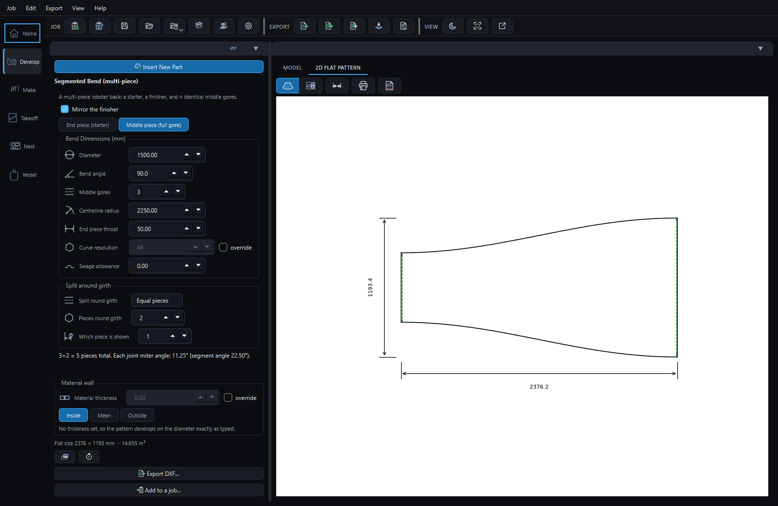
A 1500 lobster-back on 3000 × 1500 plate. Each gore is 4.7 metres round, so one click on Split to fit the sheet made every gore two plates — the fewest that fit, laps included. Plate k of every gore covers the same arc, so the joints meet.

A 1500 segmented bend with its girth split into two equal pieces, showing plate one of a middle gore
Sheet 3000 × 1500 Each plate 2379 × 1194 mm Plates per gore 2

New in the current beta

A dished head in spiral gores

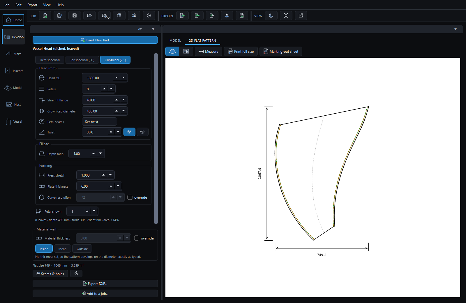
An 1800 ellipsoidal head in eight petals round a 450 crown cap, every seam turned through 30° from the cap out to the rim. The petal is developed so the girth closes at every parallel and its two welded edges come out the same length; the form says how far the seam turns, its angle at the rim and how much the press has to take up.

The Vessel Head form set to a 30 degree twist, with one spiral petal developed flat, 749 by 1068 mm
Head 1800 ellipsoidal Twist 30°, 28° at the rim Petal 749 × 1068 mm

On paper

For marking out by hand

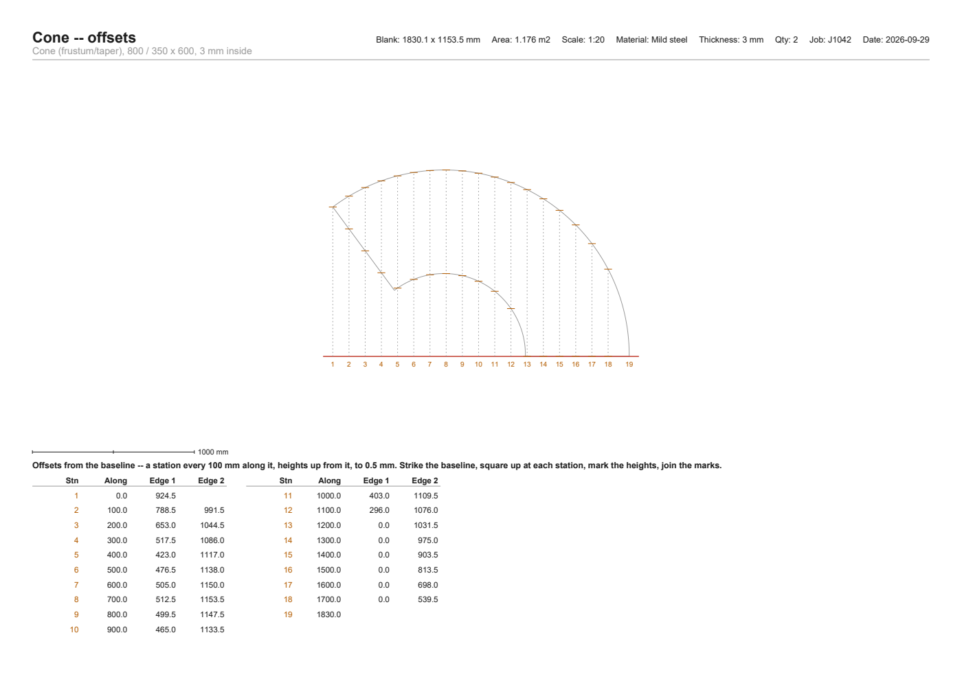
Behind the marking-out sheet comes a page of offsets from a baseline: strike the baseline, square up at each station, mark the heights, join the marks. It works for every shape, because it is read off the finished blank. A triangulated part also gets its true lengths, step by step from the seam.

The offsets page of a marking-out sheet: the cone blank with a baseline and numbered stations, and a table of heights at each station

The same cone as above. The true-length table for the general transition is here.

From the building model

An IFC model, read and reviewed

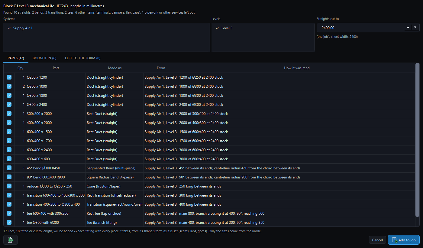
One floor of a hospital's supply ductwork from the consultant's IFC model. Each duct and fitting is listed with the shape it becomes and how its numbers were read, straights are cut to the stock length, and the diffusers and damper are set aside as bought in. Nothing reaches the job until Add to job.

The IFC import review listing 17 parts, each with the shape it is made as, where it came from in the model and how it was read
Parts 17 Bought in 6 Straights cut to 2400

Model space add-on · new

The ductwork in 3D, numbered as the job

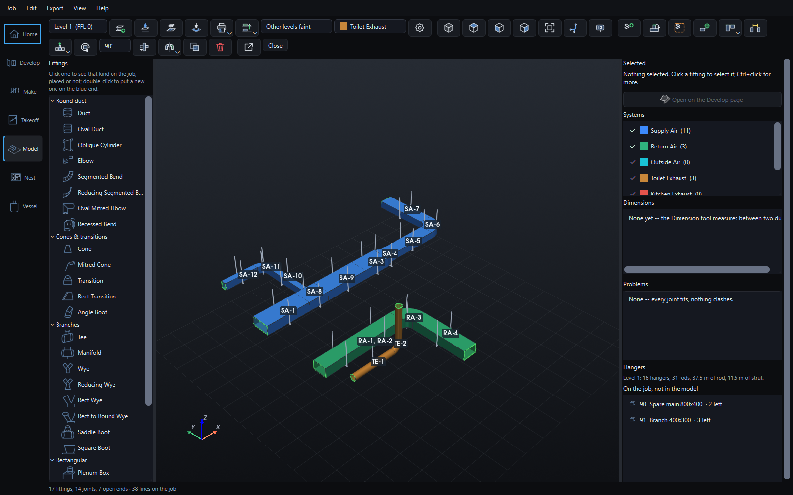
A supply main with a side-branch tee, a transition and a radius bend, a return run alongside and a toilet exhaust riser, each in its system's colour. Every label is the part number the job gives that fitting, and the problems panel says every joint fits and nothing clashes. More on Model space.

The Model page: supply, return and exhaust runs in blue, green and orange, every fitting labelled with its part number, the systems listed with their counts
Fittings 17 Joints 14 Clashes 0 Lines on the job 38

Model space add-on · new

Levels, a grid, and a dimension that holds

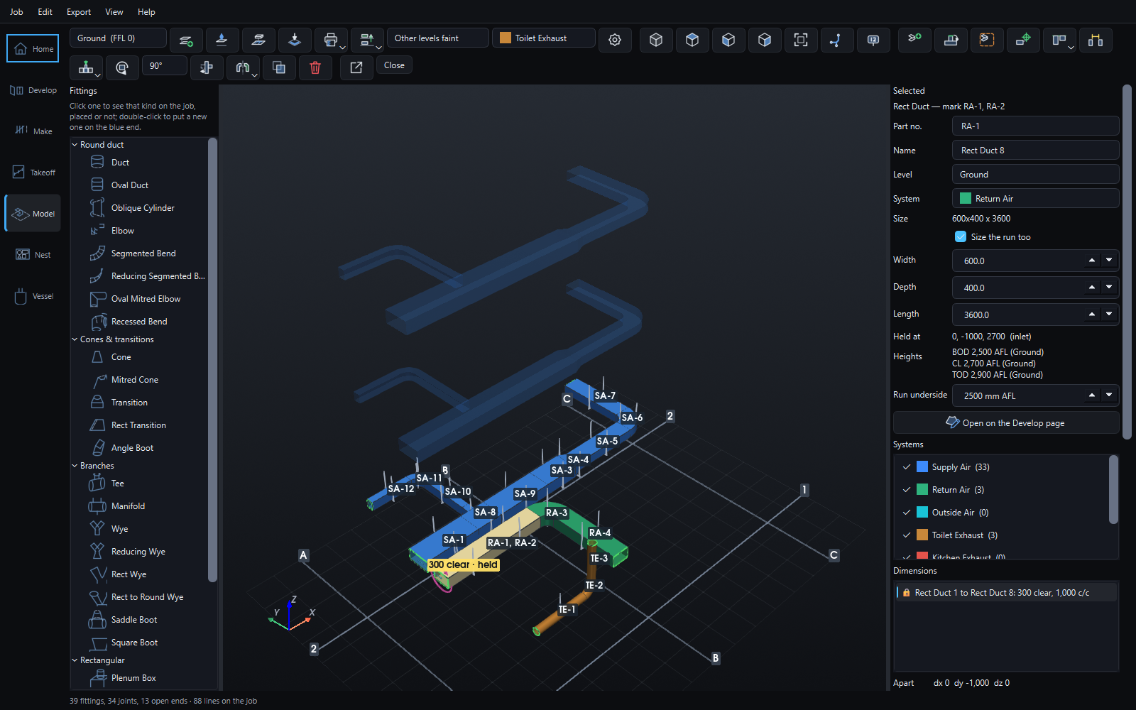
The ground floor and two typical floors above it, on a site datum, with grid lines A to C and 1 to 2. The supply has been copied up both floors and shows faint; the return is dimensioned 300 clear of the supply and locked, so widening the supply moves the return with it.

Three floors with the supply copied faintly onto the upper two, grid lines with their bubbles, and a yellow label reading 300 clear, held, between the return and the supply
Floors 3 Grid lines 5 Return to supply 300 clear, held

Model space add-on · new

The install drawing, printed from the model

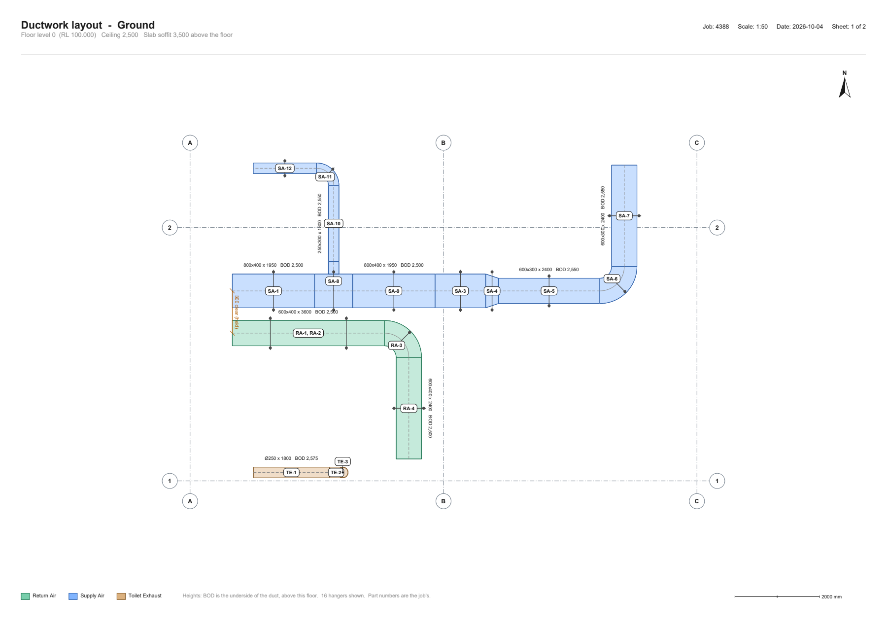
Print layout draws a floor for the installers at a stated scale: every fitting in plan in its system's colour, the job's part numbers in bubbles, each straight's size and underside height, the grid, the held dimension and every hanger. A schedule follows on the next sheet, and the same layout goes out as a DXF.

A printed ductwork layout of the ground floor at 1:50 with part numbers, sizes, underside heights, the grid and the hangers
Scale 1:50 on A3 Fittings 17 Hangers 16

Takeoff add-on

Measured and counted off the builder's PDF

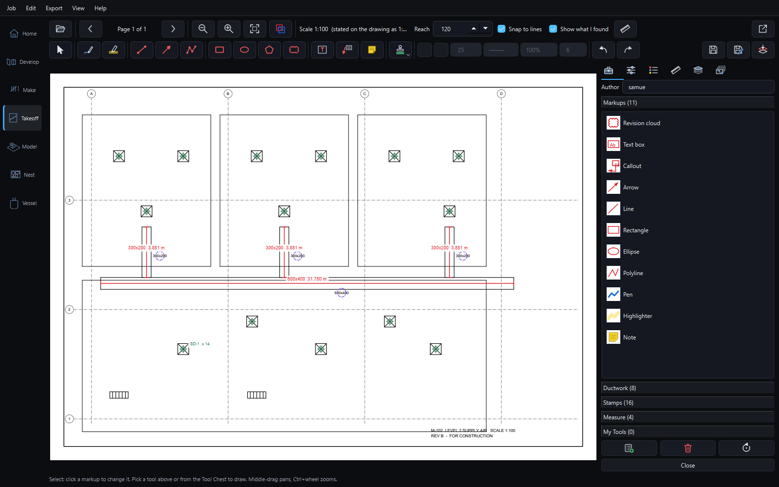
The scale read off the title block, the trunk and branches measured and labelled with the sizes written beside them, and one diffuser boxed and named SD-1: all fourteen on the sheet found and counted. Revision B can be laid over A to see what changed.

A mechanical plan in the takeoff page with the runs measured in red and a diffuser symbol counted 14 times, and the markup tools down the side
600x400 trunk 31.750 m 300x200 branches 3 × 3.881 m SD-1 × 14

Plate

A cone for the rolls

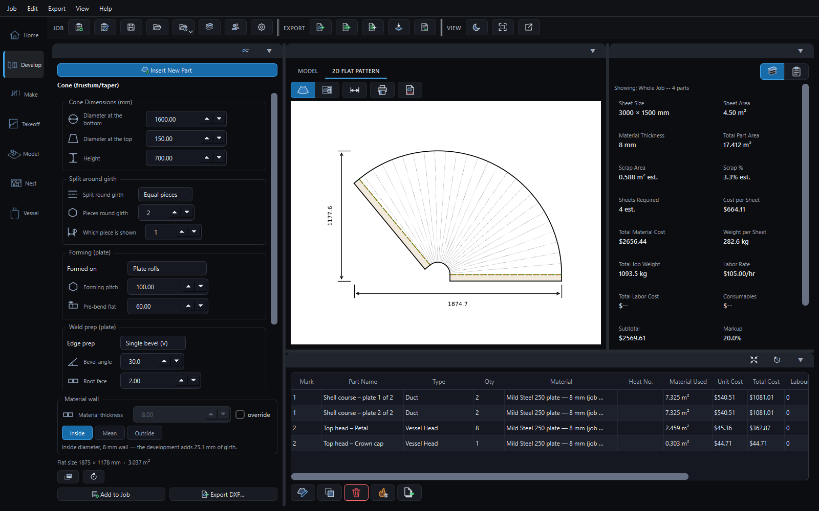
The bottom cone of a hot water tank in 8 mm plate, 1600 down to 150, split into two to fit a 3000 × 1500 plate. The roll lines run across the blank and a 60 mm pre-bend flat sits past each seam for the edge the rolls cannot reach; the seams carry a 30° single V.

A cone developed flat with roll lines across it and pre-bend flats shaded along each seam
Plate 8 mm Pre-bend flat 60 mm Half a cone 1875 × 1178 mm

Vessel calculations add-on

The nozzle checked, with the working shown

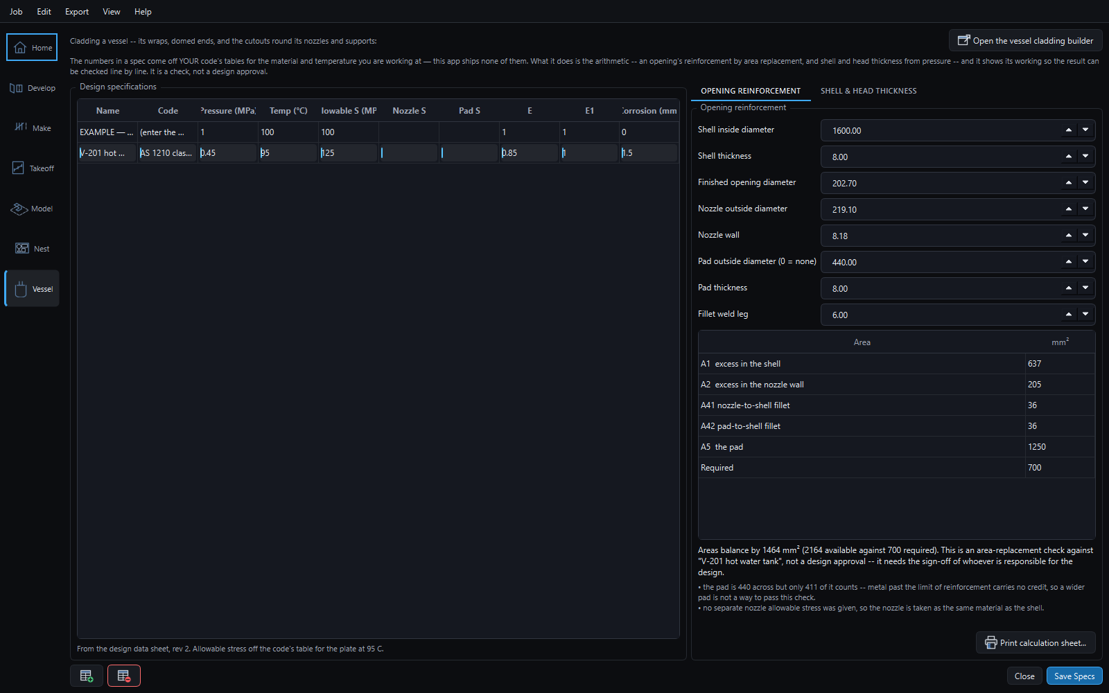
A 200 NB inlet in a 1600 shell with a 440 pad, checked by area replacement against the design spec's numbers. Every area is listed, the verdict says it needs the sign-off of whoever is responsible for the design, and Print calculation sheet writes it out for signing.

The vessel calculations page: design specs on the left, the opening reinforcement inputs and the areas A1 to A5 against the area required on the right
Required 934 mm² Available 1926 mm²

On the shop floor

A job shared with the workshop

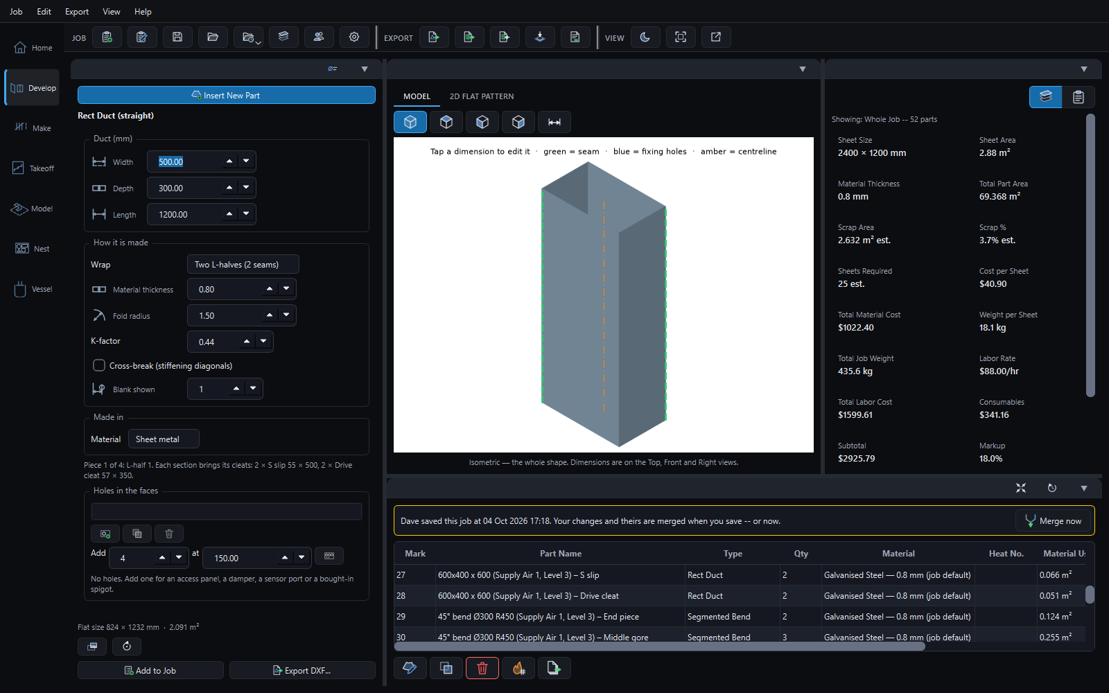
The workshop saved the job while the office had it open. The bar says who and when, and Merge now brings their parts ticked off as cut together with the office's changed quantity. Every save stays in the job's history.

The job with a yellow bar across the parts table saying another person saved it, and a Merge now button

Not everything fits on one page

Every feature is listed by the work it is for, and the tutorial walks an insulation job, an HVAC job and a plate job from start to finish in 41 of the program's own screens. Nesting I want through real jobs on real tables before I call it finished; if cutting is your end of the job, there is a tester list.

30-day trial

Try it on a part you already know the answer to.

That is the only test worth doing. Develop something you have cut before, check the girth against your own numbers, and see whether it agrees.